|
Available Languages
|

|

|
Introduction
A Seven Segment Display, is a form of electronic display device for displaying decimal numerals that is an alternative to the more complex dot matrix displays. Seven segment displays are widely used in digital clocks, electronic meters, basic calculators, and other electronic devices that display numerical information.
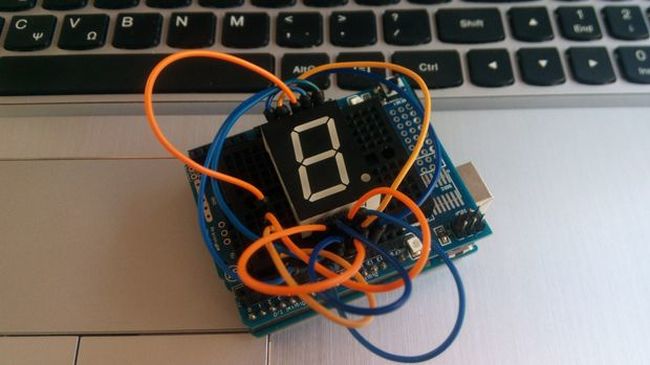
In this tutorial you will learn how to use one 7 Segment Display with Arduino uno. You will be able to print a number from 1 to 9 at the 7 segment display from the serial monitor.
Before we start, let's see more information about this type of display.
In this tutorial you will learn how to use one 7 Segment Display with Arduino uno. You will be able to print a number from 1 to 9 at the 7 segment display from the serial monitor.
Before we start, let's see more information about this type of display.
About the Seven Segment Display
|
|
|
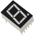
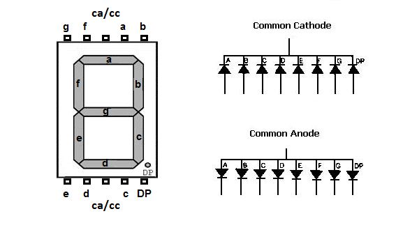
The 7 segment display consists of seven LEDs (hence its name) arranged in a rectangular fashion as shown (see first image above). Each of the seven LEDs is called a segment because when illuminated the segment forms part of a numerical digit (decimal numbers and some letters) to be displayed. An additional 8th LED (right corner) is sometimes used within the same package thus allowing the indication of a decimal point, (DP) when two or more 7-segment displays are connected together to display numbers greater than ten.
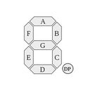
Each one of the seven LEDs in the display is given a positional segment with one of its connection pins being brought straight out of the rectangular plastic package. These individually LED pins are labelled from 'A' through to 'G' (see second image above) representing each individual LED. The other LED pins are connected together and wired to form a common pin.
The displays common pin is generally used to identify which type of 7-segment display it is. As each LED has two connecting pins, one called the “Anode” and the other called the “Cathode”, there are therefore two types of 7 segment display called "common cathode - cc" and "common anode - ca" (see third image above).
In this tutorial we will use a common cathode 7 segment display.
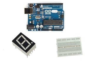
What you will need - Hardware
|
For this project you will need:Optional, you will need 7x 220 Ohm resistors, one for each led.
|
|
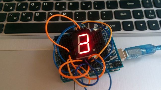
The Circuit

The connections are pretty easy, see the image above with the breadboard circuit schematic.
Pinout of 7 segment display: (read the datasheet!)
Pinout of 7 segment display: (read the datasheet!)
|
|
(if you want you can connect resistors to each pin - except "CC")
The code
Here's the code, embedded using codebender!
- numOfDigits = 1 If we have two seven segment displays we will change this to "2".
- digitPins [numOfDigits] = {4} If we have two seven segment displays, we have to add the second display CC pin to e.g. arduino pin 3, so we will change it to "{4, 3}".
- disp.setDutyCycle(50) Control brightness of display - "50" is 50% of led brightness.
- disp.writeDigit(number) Print a number from 0 to 9
1 2 3 4 5 6 7 8 9 10 11 12 13 14 15 16 17 18 19 20 21 22 23 24 25 26 27 28 29 30 31 32 33 34 35 36 37 38 39 40 41 42 43 44 45 46 47 48 49 50 51 52 53 54 | /* Arduino Tutorial - 7 Segment One 7 segment is one digit, from 0 to 9. Dev: Vasilakis Michalis // Date: 25/7/2015 // www.ardumotive.com */ //Library #include "SevenSeg.h" //Defines the segments A-G: SevenSeg(A, B, C, D, E, F, G); SevenSeg disp (10,9,8,7,6,11,12); //Number of 7 segments const int numOfDigits =1; //CC(or CA) pins of segment int digitPins [numOfDigits]={4}; //Variables int number=0; //Default number int flag; void setup() { Serial.begin(9600); //Defines the number of digits to be "numOfDigits" and the digit pins to be the elements of the array "digitPins" disp.setDigitPins ( numOfDigits , digitPins ); //Only for common cathode 7segments disp.setCommonCathode(); //Control brightness (values 0-100); disp.setDutyCycle(50); } void loop() { //Check if incoming data is available: if (Serial.available() > 0) { // If it is, we'll use parseInt() to pull out only numbers: number = Serial.parseInt(); flag=0; } //Valid range is from 1 to 9 if (number>=1 && number<=9){ //Print number to 7 segment display disp.writeDigit(number); //Print message to serial monito only once if (flag==0){ //Print number to serial monitor Serial.print("Number on 7 segment display:"); Serial.println(number); flag=1; } } } |
|
Download the code from here and open it with Arduino IDE. Inside you will also find additional libraries.
|
| ||
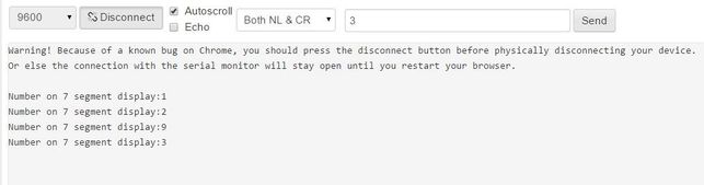
Open the serial monitor from tools menu of Arduino IDE, try to send a number from 1 to 9.
You can keep playing with that, for example, try to change disp.writeDigit(number) "number" with letter "F" (or 'b', 'd', 'A','E'). You can find more info about "SevenSeg.h" library and more available functions here.
You can keep playing with that, for example, try to change disp.writeDigit(number) "number" with letter "F" (or 'b', 'd', 'A','E'). You can find more info about "SevenSeg.h" library and more available functions here.
Well done!
You have successfully completed one more Arduino "How to" tutorial and you learned how to use one Seven Segment Display with Arduino uno. I hope you liked this, let me know in the comments.