
|
Available Languages
|

|

|
|
* Σύντομα και στα Ελληνικά
Introduction |
Published date: 11/4/2017
|
|
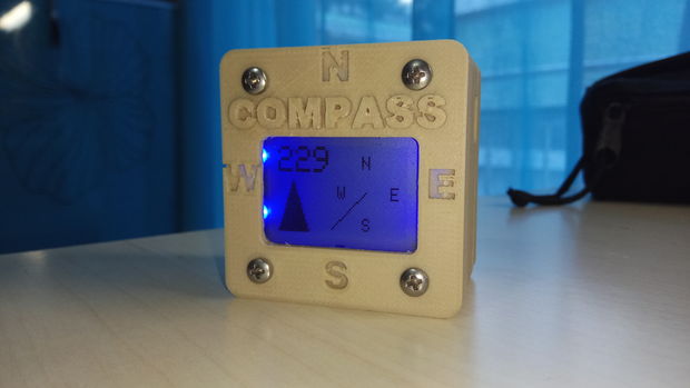
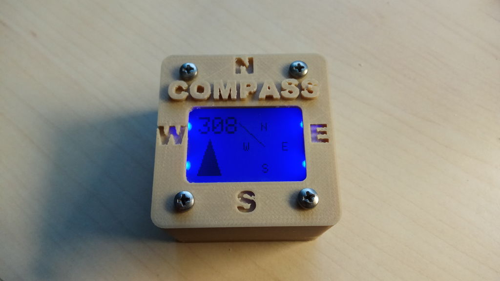
In this guide I will show you how to make your own Arduino based digital magnetic compass.
In this guide you will also find the .stl files of the 3d printed case/box. Let's get started! |

What you will need - Hardware
If you want to make the whole circuit to fit inside our 3D printed box you must buy:
If you want to make it super easy, without the 3d printed case or if you want to make it bigger to your own box you will need:
- ATmega328p (with Arduino uno bootloader)
- 28pin dip socket
- 10kΩ resistor
- 16Mhz crystal
- 2x 22pF capacitors
- HMC5883L sensor board
- Nokia 5110 display (pcb version)
- Lithium Battery Charger Module 1A - TP4056
- Rechargeable battery 3.7V (25x40mm max!)
- On/off button (with Mounting hole diameter Ø12.5mm)
If you want to make it super easy, without the 3d printed case or if you want to make it bigger to your own box you will need:
|
|
The circuit
|
|
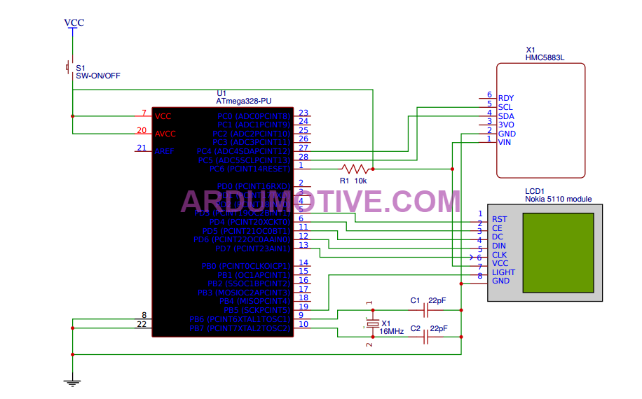
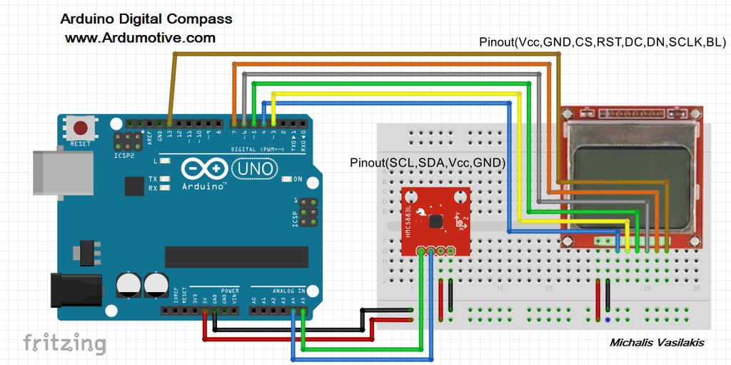
Above you will find the breadboard and electronic circuit schematic. Ι suggest you to build your circuit on (small) breadboard first. The connections are easy, just follow the pinout.
Here you can find the electronic circuit schematic on better detail than above image
About the HMC5883 sensor:
The HMC5883L sensor is a 3-axis digital magnetometer IC designed for low-field magnetic sensing. The sensor has a full-scale range of +8 to -8 Gauss and a resolution of up to 5 milli-Gauss. Communication with the HMC5883L is simple and all done through an I2C interface. That means you will need to connect power, ground and only two cables to Arduino uno board (SDA,SCL).
Note!
Because this is a magnetic compass if you put it near to battery, motors, metallic surface or magnetic field, the result will diverge from the actual.
Also make sure to use it on a flat surface!
The code
1 2 3 4 5 6 7 8 9 10 11 12 13 14 15 16 17 18 19 20 21 22 23 24 25 26 27 28 29 30 31 32 33 34 35 36 37 38 39 40 41 42 43 44 45 46 47 48 49 50 51 52 53 54 55 56 57 58 59 60 61 62 63 64 65 66 67 68 69 70 71 72 73 74 75 76 77 78 79 80 81 82 83 84 85 86 87 88 89 90 91 92 93 94 95 96 97 98 99 100 101 102 103 104 105 106 107 108 109 110 111 112 113 114 115 116 117 118 119 120 121 122 123 124 125 126 127 128 129 130 131 132 133 134 135 136 137 138 139 140 141 142 143 144 145 146 147 148 149 150 151 152 153 154 155 156 157 158 159 160 161 162 163 164 165 166 167 168 | /* Arduino 3D printed Digital Magnetic Compass using 3-Axis Digital Compass IC HMC5883L board Thanks for display graphic feature : http://lookmanowire.blogspot.gr/search/label/Electronic%20compass Ver. 1.0 / Date:2/4/2017 */ //Include libraries #include <SPI.h> #include <Wire.h> #include <Adafruit_GFX.h> //for graphics #include <Adafruit_PCD8544.h> //for Nokia 5110 lcd #include <Adafruit_HMC5883_U.h>//for compass #include <Adafruit_Sensor.h> //Common sensor library //Init Display (SCLK, DIN, D/C, CS, RST) Adafruit_PCD8544 display = Adafruit_PCD8544(7, 6, 5, 4, 3); //Init HMC5883L sensor Adafruit_HMC5883_Unified compass = Adafruit_HMC5883_Unified(12345); //Constants const int lcdLight = 13; //BL pin of LCD to arduino pin 13 (BL = Back Light) // For 2nd display mode: int r = 22; // radius of compass rose int x0= 58; // x-origin int y0 = 24; // y-origin void setup() { pinMode(lcdLight, OUTPUT); // lcd led digitalWrite(lcdLight, HIGH); //Turn on backlight - Can also be controlled with a button compass.begin(); Wire.begin(); display.begin(); display.setContrast(60); //Print a welcome message in startup for 6sec.////////// digitalWrite(lcdLight,HIGH); display.clearDisplay(); // clears the screen and buffer display.setTextColor(BLACK); display.setCursor(0,2); display.print(" ARDUMOTIVE "); display.setCursor(0,13); display.print(" ArduinoBased "); display.setCursor(0,23); display.print(" Compass "); display.setCursor(0,33); display.print(" 3D Printed "); display.display(); // show splashscreen delay(6000); ///////////////////////////////////////////////////////// display.clearDisplay(); // clears the screen and buffer } void loop() { //Reading and calculate degrees: ///////////////////////////////////// //Get new sensor value every time that loop starting again sensors_event_t event; compass.getEvent(&event); //Variable heading stores value in radians float heading = atan2(event.magnetic.y, event.magnetic.x); // Once you have your heading, you must then add your 'Declination Angle', which is the 'Error' of the compassnetic field in your location. // Find yours here: http://www.magnetic-declination.com/ // Mine is: -13* 2' W, which is ~13 Degrees, or (which we need) 0.22 radians float declinationAngle = 0.43; //<--Change 0.22 with yours. If you can't find your declination juct delete those lines ;) heading += declinationAngle; // Correct for when signs are reversed. if(heading < 0) heading += 2*PI; // Check for wrap due to addition of declination. if(heading > 2*PI)heading -= 2*PI; // Convert radians to degrees for readability. float headingDegrees = heading * 180/M_PI; //Convert float to int int angle=(int)headingDegrees; ////////////////////////////////////////////////////////////////////////// display.clearDisplay(); // Just in case... // Calculation of compass needle on lcd pointing to the direction DrawCircle(angle); //call DrawCircle function // Display actual heading display.setTextSize(2); display.setTextColor(BLACK); display.setCursor(0,0); display.println(angle); display.setTextSize(1); display.setTextColor(BLACK); display.setCursor(x0-2,5); display.println("N"); display.setTextSize(1); display.setTextColor(BLACK); display.setCursor((x0+r)-6,y0-3); display.println("E"); display.setTextSize(1); display.setTextColor(BLACK); display.setCursor(x0-2,y0+r-8); display.println("S"); display.setTextSize(1); display.setTextColor(BLACK); display.setCursor((x0-r)+4,y0-3); display.println("W"); // Triangle for direction display.drawTriangle(0, 46, 20, 46, 10, 18, BLACK); display.fillTriangle (0, 46, 20, 46, 10, 18, BLACK); display.display(); delay(500); //print new value every 0.5sec }/// end of program //////////// Functions //////////// ////Draw circle and print letters to display - 1st Display Mode void DrawCircle(int angleActual) { if (angleActual >= 0 && angleActual <=45) { // 0-45 degrees int angle = angleActual/2; display.drawLine(x0, y0, x0+angle, y0-r, BLACK); } else if (angleActual >45 && angleActual <=90) { // 46-90 degrees int angle = (angleActual-45)/2 ; display.drawLine(x0, y0, x0+r, (y0-r)+angle, BLACK); } else if (angleActual >90 && angleActual <=135) { // 91-135 degrees int angle = (angleActual-90)/2; display.drawLine(x0, y0, x0+r, y0+angle, BLACK); } else if (angleActual >135 && angleActual <=180) { // 136-180 degrees int angle = (angleActual-135)/2; display.drawLine(x0, y0, (x0+r)-angle, y0+r, BLACK); } else if (angleActual >180 && angleActual <=225) { // 181-225 degrees int angle = (angleActual-180)/2; display.drawLine(x0, y0, x0-angle, y0+r, BLACK); } else if (angleActual >225 && angleActual <=270) { // 226-270 degrees int angle = (angleActual-225)/2; display.drawLine(x0, y0, x0-r, (y0+r)-angle, BLACK); } else if (angleActual >270 && angleActual <=315) { // 271-315 degrees int angle = (angleActual-270)/2; display.drawLine(x0, y0, x0-r, y0-angle, BLACK); } else if (angleActual >315 && angleActual <=360) { // 316-360 degrees int angle = (angleActual-315)/2; display.drawLine(x0, y0, (x0-r)+angle, y0-r, BLACK); } } |
Download the code from here and open it with Arduino IDE. Inside you will also find all necessary libraries!
Program the ATmega328p with your Arduino uno board, detach it from it and plug it on your custom circuit.
(if you are using a breadboard for testing, here you must see that everything working fine)
Special note: Code line: 60 to 63
// Once you have your heading, you must then add your 'Declination Angle', which is the 'Error' of the compassnetic field in your location.
// Find yours here: http://www.magnetic-declination.com/ // Mine is: -13* 2' W, which is ~13 Degrees, or (which we need) 0.22 radians
float declinationAngle = 0.22; //<--Change 0.22 with yours. If you can't find your declination just delete those lines ;)
| digital_compass.zip |
3D Printer Files
|
|
|
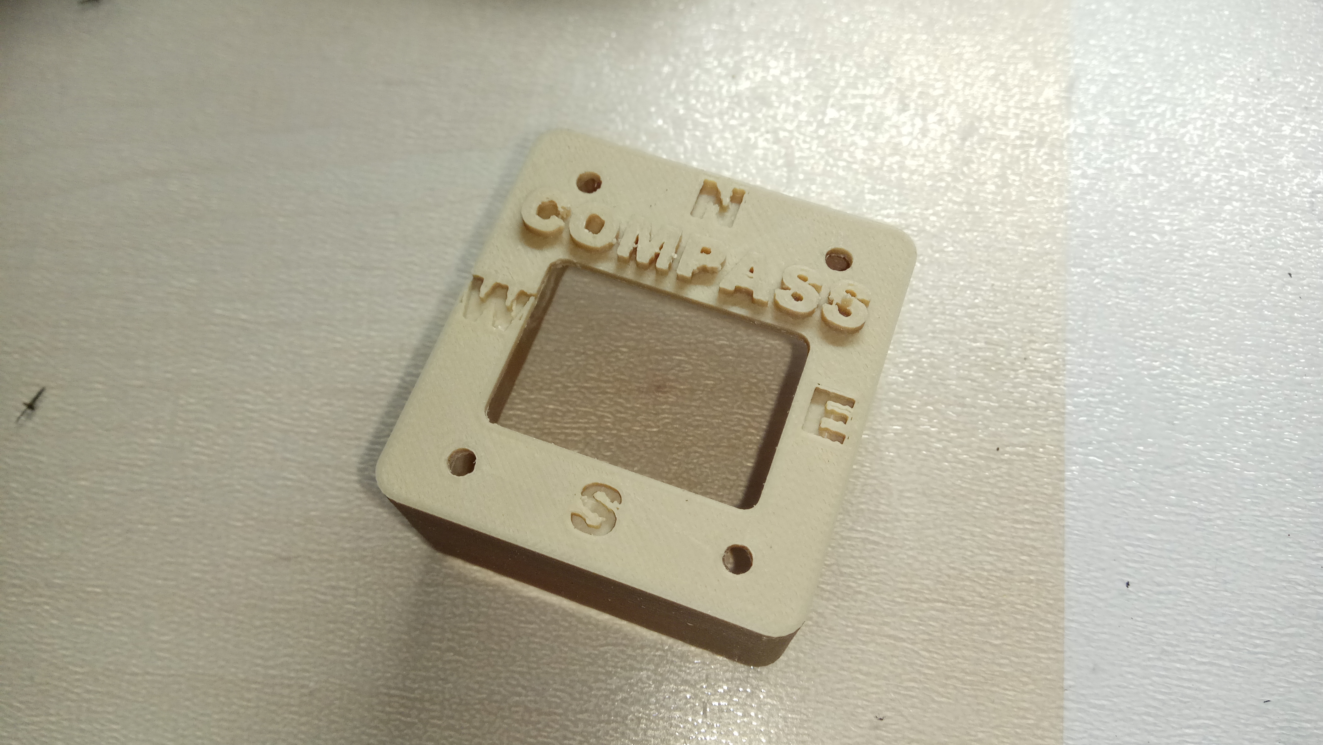
Use full support on your printing procedure.
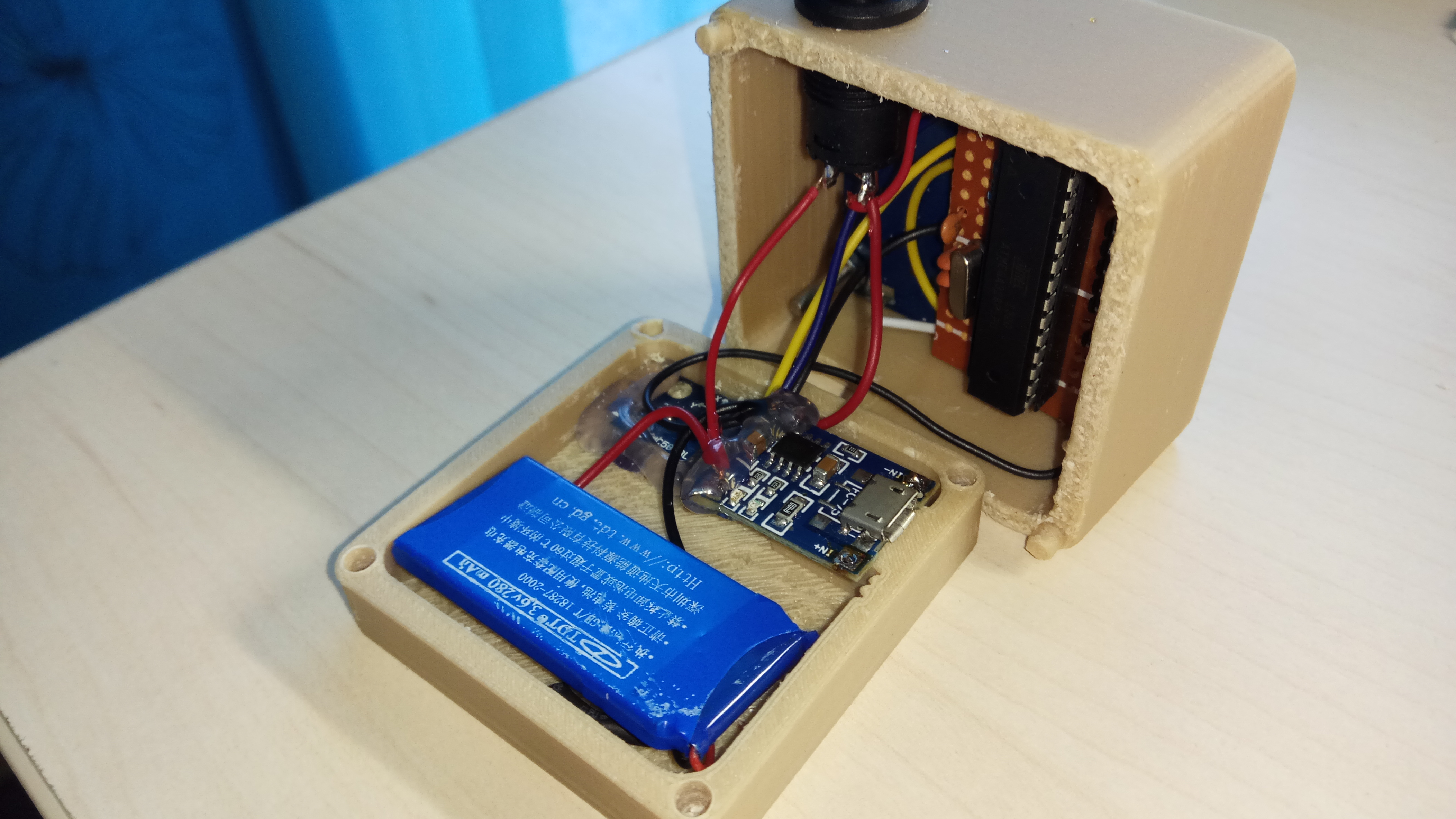
Above image will help you to understand how you can fit them all inside it. Make sure that the sensor is glued well on the bottom part - lid and the "x" label looking to the same direction as "N" letter on the top of the main part.
|
| ||||||
Well Done!
Well...that's it!
I hope you liked this, let me know in the comments!
I would also like to see some photos with your new 3D printed Arduino Compass!
I hope you liked this, let me know in the comments!
I would also like to see some photos with your new 3D printed Arduino Compass!