
|
Available Languages
|

|

|
Introduction |
Published date: 22/3/2019
|
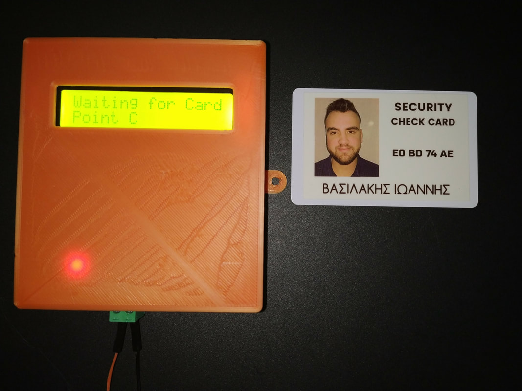
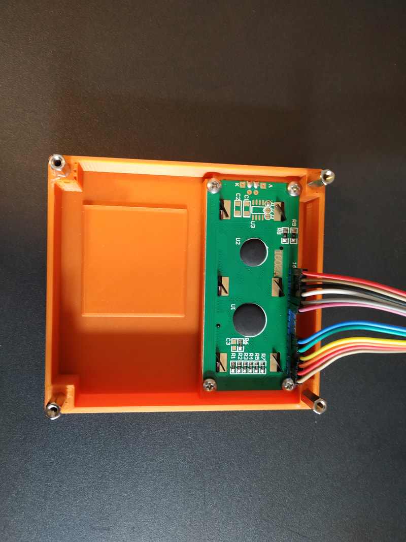
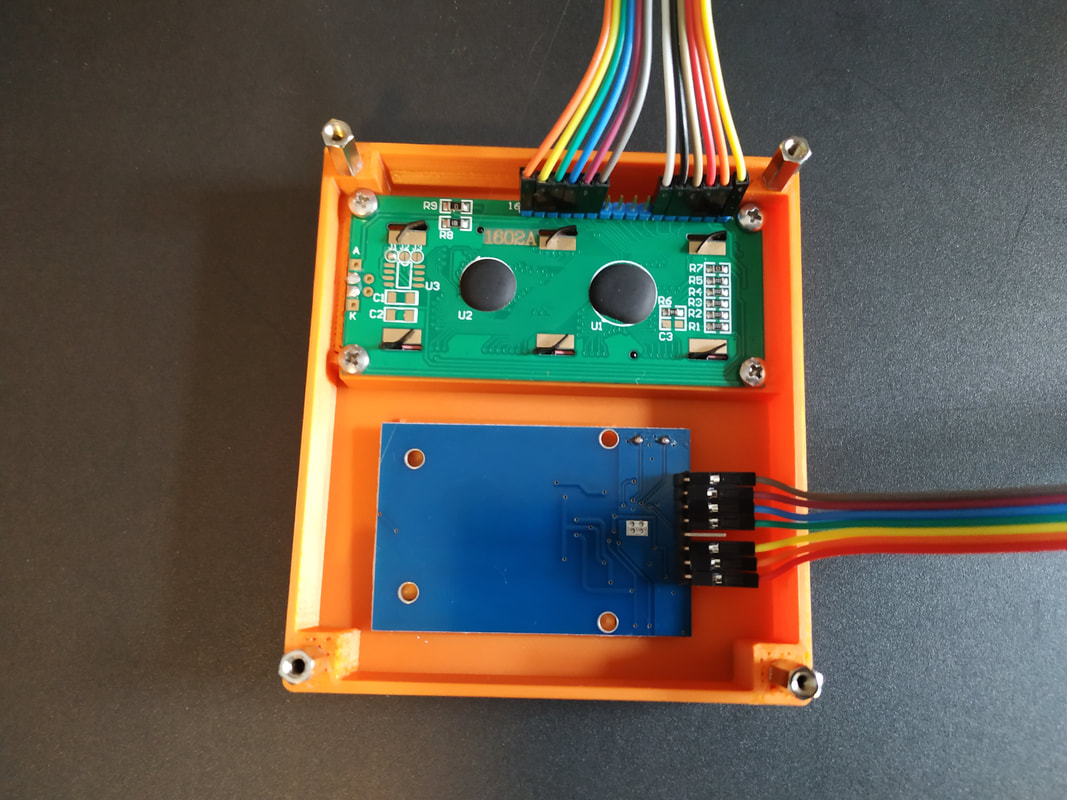
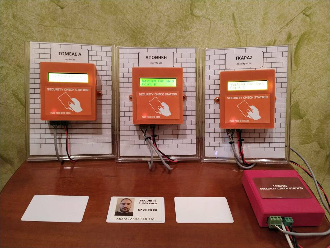
In this DIY guide I will show you how to make your own security check system based on Arduino!
You can use this system in areas with security guards (e.g. warehouses, malls, open areas). Every guard will have a personal RFID card with a unique ID number. When a security guard pass his cards over the Check point station - the ID and the current time/date will be stored inside controller memory (EEPROM). The security guard inside the "Control Room" can read the report of all check point stations with only one click!
This project started out as a Bachelor's thesis by me - John Vasilakis (supervised by Grigoris Tziallas) - Electronic Engineering Department of Stereas Elladas University. We are supporting the open hardware - software community so this project will be marked as an open-source. Before share/copy/change anything of below guide, make sure to read and agree with the CC BY-NC-SA licence agreement!
We used the RFID technology to read scanned card and the RS485 electrical data bus protocol for communication. In this project I decided to make my own PCB that is based on Arduino UNO microcontroller - Atmega328p.
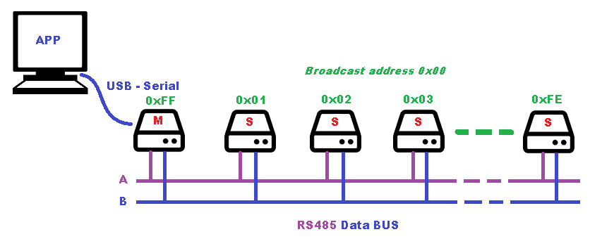
We can have up to 254 slave-check point stations and one master station in the RS485 data bus. The master station is communicating with one computer in security room via serial USB port. We will describe the communication protocol in the following steps!
Let's get started.
You can use this system in areas with security guards (e.g. warehouses, malls, open areas). Every guard will have a personal RFID card with a unique ID number. When a security guard pass his cards over the Check point station - the ID and the current time/date will be stored inside controller memory (EEPROM). The security guard inside the "Control Room" can read the report of all check point stations with only one click!
This project started out as a Bachelor's thesis by me - John Vasilakis (supervised by Grigoris Tziallas) - Electronic Engineering Department of Stereas Elladas University. We are supporting the open hardware - software community so this project will be marked as an open-source. Before share/copy/change anything of below guide, make sure to read and agree with the CC BY-NC-SA licence agreement!
We used the RFID technology to read scanned card and the RS485 electrical data bus protocol for communication. In this project I decided to make my own PCB that is based on Arduino UNO microcontroller - Atmega328p.
We can have up to 254 slave-check point stations and one master station in the RS485 data bus. The master station is communicating with one computer in security room via serial USB port. We will describe the communication protocol in the following steps!
Let's get started.
What you will need - Hardware Part List
|
For Master Station you will need: ----> Or use an Arduino board with breadboard Power by 5V power adapter
|
For every Slave - Sensor Station you will need:
|
*You will also need a TTL to USB module or an Arduino UNO board for the programming procedure.
The circuit at EasyEDA, the free online circuit design platform
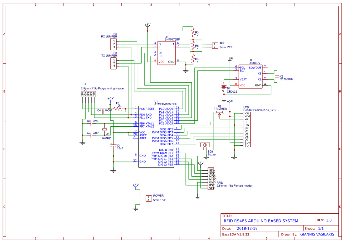
Circuit
|
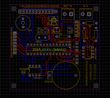
PCB
|
EasyEDA is a free, zero- install, cloud-based EDA tool, designed to give electrical engineers, educators, engineering students and electronics hobbyists an Easier EDA Experience. It is easy to use circuit design, circuit simulator and PCB design that runs in your web browser.
Arduino Connection Pins
|
LCD
RFID
RTC
SN75176
Buzzer to Arduino Pin 8 |
|

The code
Connect your circuit with TTL to USB module with 5 cables to the programming header. The pins RX and TX must be cross-connected.
NOTE: If you are using the Arduino UNO board make sure to remove the ATmega328 IC from it first and connect the headers RX to RX and TX to TX pins of the board. The RS pin must be connected to Arduino UNO reset pin.
NOTE: If you are using the Arduino UNO board make sure to remove the ATmega328 IC from it first and connect the headers RX to RX and TX to TX pins of the board. The RS pin must be connected to Arduino UNO reset pin.
Communication protocol for RS485 data bus
Command format:
Update time and date to all slave stations:
<00TYYYYMMDDhhmm> example: <00T201903211535> will set clock to 15:35 21/03/2019
Update card list to all slave stations:
<00CiXXXXXXXX>, where ' i' is the index from 0 to 9 (up to 10 cards) and 'XXXXXXXX' the ID of the RFID card.
Example: <00C2FESDBEDF> will store the ID "FESDBEDF" to position 3 of card list.
Read time from slave station:
Master will send: <ADt> where "AD" is the address of station - from 01 to FE
Slave will answer: <FFtDD/MM/YYYY hh:mm>
Example: Ask slave with address "0A" <0At> --> <FFt21/03/2019 15:35>
Read card from slave station:
Master will send: <ADci> where "AD" is the address of station - from 01 to FE and 'i' the index from 0 to 9
Slave will answer: <FFciXXXXXXXX>
Example: Ask slave with address "05" for card ID at index 4 <05c4> --> <FFc4FESDBEDF>
Read report from slave station:
Master will send: <ADr> where "AD" is the address of station - from 01 to FE
Slave will answer: <FFrXXXXXXXXDD/MM/YYYY hh:mm>
Example: Ask slave with address "15" for last report: <FFrFESDBEDF21/03/2019 15:35>
- Starting message char: <
- Destination Port Address: 00 For all slave stations, FF for master or 01 to FE for slave unit
- Command char: T , C, t, c, r
- Message
- Ending message char: >
Update time and date to all slave stations:
<00TYYYYMMDDhhmm> example: <00T201903211535> will set clock to 15:35 21/03/2019
Update card list to all slave stations:
<00CiXXXXXXXX>, where ' i' is the index from 0 to 9 (up to 10 cards) and 'XXXXXXXX' the ID of the RFID card.
Example: <00C2FESDBEDF> will store the ID "FESDBEDF" to position 3 of card list.
Read time from slave station:
Master will send: <ADt> where "AD" is the address of station - from 01 to FE
Slave will answer: <FFtDD/MM/YYYY hh:mm>
Example: Ask slave with address "0A" <0At> --> <FFt21/03/2019 15:35>
Read card from slave station:
Master will send: <ADci> where "AD" is the address of station - from 01 to FE and 'i' the index from 0 to 9
Slave will answer: <FFciXXXXXXXX>
Example: Ask slave with address "05" for card ID at index 4 <05c4> --> <FFc4FESDBEDF>
Read report from slave station:
Master will send: <ADr> where "AD" is the address of station - from 01 to FE
Slave will answer: <FFrXXXXXXXXDD/MM/YYYY hh:mm>
Example: Ask slave with address "15" for last report: <FFrFESDBEDF21/03/2019 15:35>
Communication sketch
Master
Code for the master station unit. The "Master Station" is responsible for the communication between "Slave stations" via RS485 data bus. It also communicate via serial port with the software that is running to "control room" computer.
1 2 3 4 5 6 7 8 9 10 11 12 13 14 15 16 17 18 19 20 21 22 23 24 25 26 27 28 29 30 31 32 33 34 35 36 37 38 39 40 41 42 43 44 45 46 47 48 49 50 51 52 53 54 55 56 57 58 59 60 61 62 63 64 65 66 67 68 69 70 71 72 73 74 75 76 77 78 79 80 81 82 83 84 85 86 87 88 89 90 91 92 93 94 95 96 97 98 99 100 101 102 103 104 105 106 107 108 109 110 111 112 113 114 115 116 117 118 119 120 121 122 123 124 125 126 127 128 | #include <SPI.h> #include <SoftwareSerial.h> #include <MFRC522.h> #include <Wire.h> //Buzzer #define buzzer 8 //RS485 #define rs485_RX A0 #define rs485_TX A1 #define rs485_DE A2 #define rs485_RE A3 SoftwareSerial rs485(rs485_RX, rs485_TX); // RX, TX String MASTER_PORT = "FF"; String newCard=""; //RFID #define SS_PIN 10 #define RST_PIN 9 MFRC522 mfrc522(SS_PIN, RST_PIN); char incomingByte; String command; boolean messageCompleted = false; boolean newMessage = false; void setup() { pinMode(rs485_RE, OUTPUT); pinMode(rs485_DE, OUTPUT); digitalWrite(rs485_RE, LOW); digitalWrite(rs485_DE, LOW); Serial.begin(9600); rs485.begin(19200); SPI.begin(); // Initiate SPI bus mfrc522.PCD_Init(); // Initiate MFRC522 } void loop() { serialCommunication(); readCard(); rs485Communication(); } void readCard() { if ( ! mfrc522.PICC_IsNewCardPresent()) { return; } // Select one of the cards if ( ! mfrc522.PICC_ReadCardSerial()) { return; } //Show UID on serial monitor String card = ""; for (byte i = 0; i < mfrc522.uid.size; i++) { card.concat(String(mfrc522.uid.uidByte[i] < 0x10 ? " 0" : " ")); card.concat(String(mfrc522.uid.uidByte[i], HEX)); } card.toUpperCase(); card = card.substring(1); card.replace(" ", ""); newCard = card; tone(buzzer,500,300); } void serialCommunication() { if (rs485.available()) { incomingByte = rs485.read(); if (incomingByte == '>') { messageCompleted = true; newMessage = false; } else if (incomingByte == '<') { newMessage = true; } if (newMessage) { command.concat(incomingByte); } } if (messageCompleted) { if (command.substring(1, 3) == MASTER_PORT) { if (command.charAt(3) == 't') { Serial.println(command.substring(4)); } else if (command.charAt(3) == 'c') { String index = command.substring(4,5); String card = command.substring(5); card.replace("xxxxxxxx","NOT SET"); Serial.println(index+": "+card); } //Report last check to master - time and card id else if (command.charAt(3) == 'r') { Serial.println(command.substring(4)); } } command = ""; messageCompleted = false; } } void rs485Communication(){ if (Serial.available()) { incomingByte = Serial.read(); if (incomingByte == '>') { messageCompleted = true; newMessage = false; } else if (incomingByte == '<') { newMessage = true; } if (newMessage) { command.concat(incomingByte); } } if (messageCompleted) { if (command.substring(1, 3) != MASTER_PORT) { digitalWrite(rs485_DE,HIGH); rs485.print(command+">"); } else{ Serial.println(newCard); newCard=""; } command = ""; messageCompleted = false; } digitalWrite(rs485_DE,LOW); } |
Slave
Code for the slave station units. Every "Slave Station" - check point unit has a unique address. Edit the variable "PORT" (line 25) with hex value of unit address - value from 01 to FE (total of 254 stations). Also change the "name" of the current station by editing the variable "point" at line 24.
Every check point can store to EEPROM memory up to 10 card IDs. If the security card exist, the ID and time-stamp will be saved to EEPROM memory.
Every check point can store to EEPROM memory up to 10 card IDs. If the security card exist, the ID and time-stamp will be saved to EEPROM memory.
1 2 3 4 5 6 7 8 9 10 11 12 13 14 15 16 17 18 19 20 21 22 23 24 25 26 27 28 29 30 31 32 33 34 35 36 37 38 39 40 41 42 43 44 45 46 47 48 49 50 51 52 53 54 55 56 57 58 59 60 61 62 63 64 65 66 67 68 69 70 71 72 73 74 75 76 77 78 79 80 81 82 83 84 85 86 87 88 89 90 91 92 93 94 95 96 97 98 99 100 101 102 103 104 105 106 107 108 109 110 111 112 113 114 115 116 117 118 119 120 121 122 123 124 125 126 127 128 129 130 131 132 133 134 135 136 137 138 139 140 141 142 143 144 145 146 147 148 149 150 151 152 153 154 155 156 157 158 159 160 161 162 163 164 165 166 167 168 169 170 171 172 173 174 175 176 177 178 179 180 181 182 183 184 185 186 187 188 189 190 191 192 193 194 195 196 197 198 199 200 201 202 203 204 205 206 207 208 209 210 211 212 213 214 215 216 217 218 219 220 221 222 223 224 225 226 227 228 229 230 231 232 233 234 235 236 237 238 239 240 241 242 243 244 245 246 247 248 249 250 251 252 253 254 255 256 257 258 259 260 261 262 263 264 265 266 267 268 269 270 271 272 273 274 275 276 277 278 279 280 281 | #include <SPI.h> #include <MFRC522.h> #include <LiquidCrystal.h> #include <Wire.h> #include "RTClib.h" #include <SoftwareSerial.h> #include <EEPROM.h> #define rs485_RX A0 #define rs485_TX A1 #define rs485_DE A2 #define rs485_RE A3 SoftwareSerial rs485(rs485_RX, rs485_TX); // RX, TX //RFID #define SS_PIN 10 #define RST_PIN 9 MFRC522 mfrc522(SS_PIN, RST_PIN); String cards[10] = {"", "", "", "", "", "", "", "", "", ""}; String check; String check_card; String check_time; String point = "Point A"; //Point B, Point C String PORT = "01"; //FROM 01,02,03 TO FE - Total of 254 Slave stations String MASTER_PORT = "FF"; //Time RTC_DS1307 rtc; String currentTime, DD, MM, YYYY, hh, mm; //LCD LiquidCrystal lcd(2, 3, 4, 5, 6, 7); //Buzzer #define buzzer 8 //Serial Communication char incomingByte; String command; boolean messageCompleted = false; boolean newMessage = false; void setup() { pinMode(rs485_RE, OUTPUT); pinMode(rs485_DE, OUTPUT); digitalWrite(rs485_RE, LOW); digitalWrite(rs485_DE, LOW); Serial.begin(9600); // Initiate a serial communication rs485.begin(19200); //RFID SPI.begin(); // Initiate SPI bus mfrc522.PCD_Init(); // Initiate MFRC522 //RTC if (! rtc.begin()) { Serial.println("Couldn't find RTC"); while (1); } if (! rtc.isrunning()) { Serial.println("RTC is NOT running!"); } //LCD lcd.begin(16, 2); //Buzzer pinMode(buzzer, OUTPUT); //Read last check from EEPROM memory (card id and timestamp) delay(10); check_card = readFromMemory(0, 8); delay(10); check_time = readFromMemory(10, 16); delay(10); //Read Card id list from memory for (int i = 0; i < 10; i++) { cards[i] = readFromMemory(30 + (i * 10), 8); //storeInMemory(30 + (i*10), "xxxxxxxx"); delay(10); Serial.println(cards[i]); } Serial.println("System is up and running"); } void setTime(int YYYY, int MM, int DD, int hh, int mm) { rtc.adjust(DateTime(YYYY, MM, DD, hh, mm, 0)); } void readTime() { //DAY DateTime now = rtc.now(); if (now.day() <= 9) { DD = "0" + String(now.day()); } else { DD = String(now.day()); } //MONTH if (now.month() <= 9) { MM = "0" + String(now.month()); } else { MM = String(now.month()); } //HOUR if (now.hour() <= 9) { hh = "0" + String(now.hour()); } else { hh = String(now.hour()); } //MINUTE if (now.minute() <= 9) { mm = "0" + String(now.minute()); } else { mm = String(now.minute()); } //YEAR if (now.year()) { YYYY = String(now.year()); } currentTime = DD + "/" + MM + "/" + YYYY + " " + hh + ":" + mm; } void checkCard() { if ( ! mfrc522.PICC_IsNewCardPresent()) { check = ""; return; } // Select one of the cards if ( ! mfrc522.PICC_ReadCardSerial()) { check = ""; return; } //Show UID on serial monitor String card = ""; for (byte i = 0; i < mfrc522.uid.size; i++) { card.concat(String(mfrc522.uid.uidByte[i] < 0x10 ? " 0" : " ")); card.concat(String(mfrc522.uid.uidByte[i], HEX)); } card.toUpperCase(); card = card.substring(1); card.replace(" ", ""); for (int i = 0; i < 10; i++) { if (card == cards[i]) { check = "VALID: " + String(card); check_card = String(card); check_time = currentTime; storeInMemory(0, check_card); //Start store card id from memory addr 0 storeInMemory(10, check_time); //Start store time stamp from memory addr 10 return; } else { check = "Card Not found..."; } } } void printLCD(String line1, String line2) { lcd.clear(); lcd.setCursor(0, 0); lcd.print(line1); lcd.setCursor(0, 1); lcd.print(line2); } void buzzerTone() { tone(buzzer, 1000); // Send 1KHz sound signal... delay(1000); // ...for 1 sec noTone(buzzer); // Stop sound... } void storeInMemory(char addr, String data) { int _size = data.length(); int i; for (i = 0; i < _size; i++) { EEPROM.write(addr + i, data[i]); } EEPROM.write(addr + _size, '\0'); //Add termination null character for String Data } String readFromMemory(char addr, int size) { int i; char data[size + 1]; int len = 0; unsigned char k; k = EEPROM.read(addr); while (len < size) //Read until null character { k = EEPROM.read(addr + len); data[len] = k; len++; } data[len] = '\0'; return String(data); } void serialCommunication() { if (rs485.available()) { incomingByte = rs485.read(); if (incomingByte == '>') { messageCompleted = true; newMessage = false; } else if (incomingByte == '<') { newMessage = true; } if (newMessage) { command.concat(incomingByte); } } if (messageCompleted) { if (command.substring(1, 3) == PORT || command.substring(1, 3) == "00" ) { //Set time if (command.charAt(3) == 'T') { int YYYY = (command.substring(4, 8)).toInt(); int MM = (command.substring(8, 10)).toInt(); int DD = (command.substring(10, 12)).toInt(); int hh = (command.substring(12, 14)).toInt(); int mm = (command.substring(14)).toInt(); setTime(YYYY, MM, DD, hh, mm); } //Set cards ids else if (command.charAt(3) == 'C') { int index = (command.substring(4, 5)).toInt(); String id = command.substring(5); cards[index] = id; //Store in memory! storeInMemory(30 + (index * 10), id); //Start store card id from memory addr 30 } } if (command.substring(1, 3) == PORT) { //Report time of this slave station to master if (command.charAt(3) == 't') { digitalWrite(rs485_DE, HIGH); rs485.println("<" + MASTER_PORT + "t" + currentTime + ">"); digitalWrite(rs485_DE, LOW); } //Report card ids of this slave station to master else if (command.charAt(3) == 'c') { int index = (command.substring(4,5)).toInt(); String MSG = "<" + MASTER_PORT + "c"+String(index); MSG += cards[index] + ">"; digitalWrite(rs485_DE, HIGH); rs485.println(MSG); digitalWrite(rs485_DE, LOW); } //Report last check to master - time and card id else if (command.charAt(3) == 'r') { digitalWrite(rs485_DE, HIGH); rs485.println("<" + MASTER_PORT + "r" + check_card + " " + check_time + ">"); digitalWrite(rs485_DE, LOW); } } command = ""; messageCompleted = false; } } void loop() { serialCommunication(); checkCard(); printLCD("Waiting for Card", point); readTime(); if (check != "") { printLCD(currentTime, check); buzzerTone(); delay(2000); } } |
|
Download the code from here and open it with Arduino IDE. Inside you will also find the library file.
|
| ||
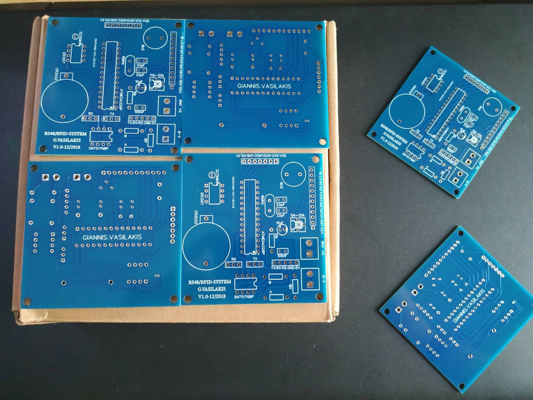
JLCPCB - Make your own circuit boad from 2$!
Enter here to produce your PCB board!
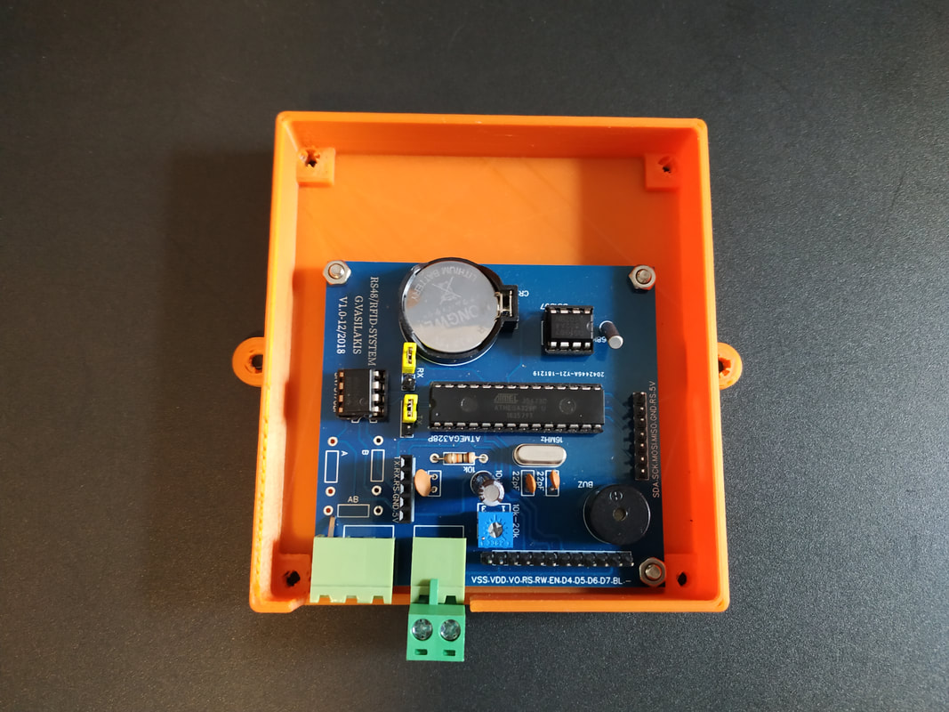
Use JLCPCB for $2 PCB Fabrication & 2-day Build Time, the quality is really good, check the below photo of our pcb board.
Use JLCPCB for $2 PCB Fabrication & 2-day Build Time, the quality is really good, check the below photo of our pcb board.
| gerber_new_pcb_20190319185047.zip |
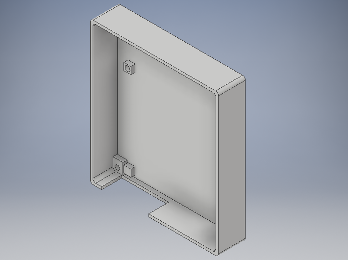
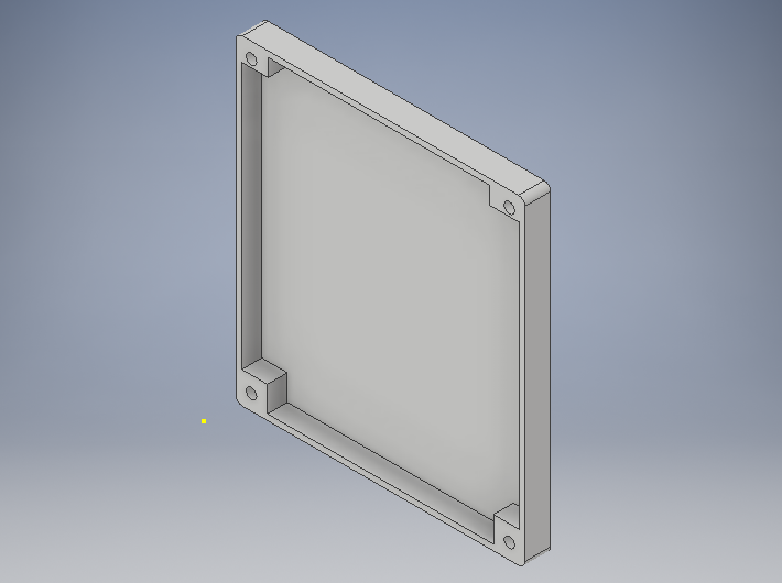
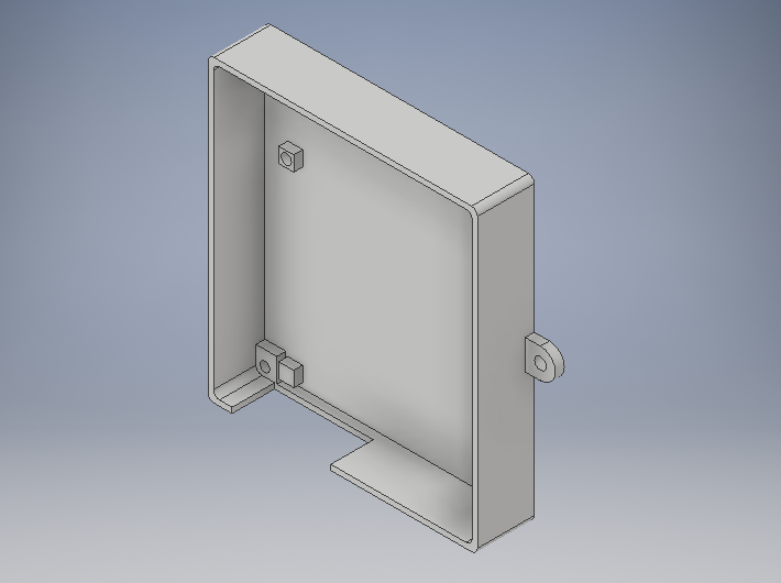
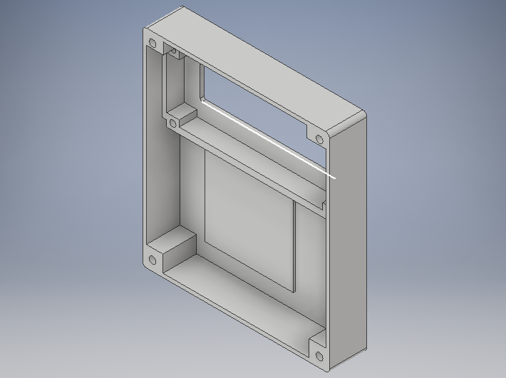
3D Parts
|
Master B
|
Slave A
|
Slave B
|
| 3dfiles.zip |
Windows Software
| software.zip |
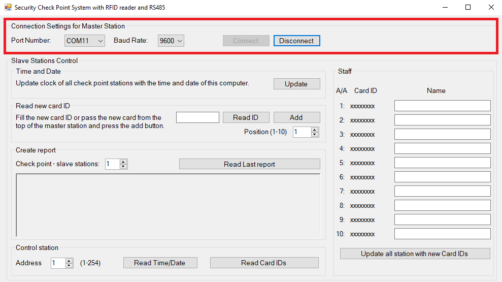
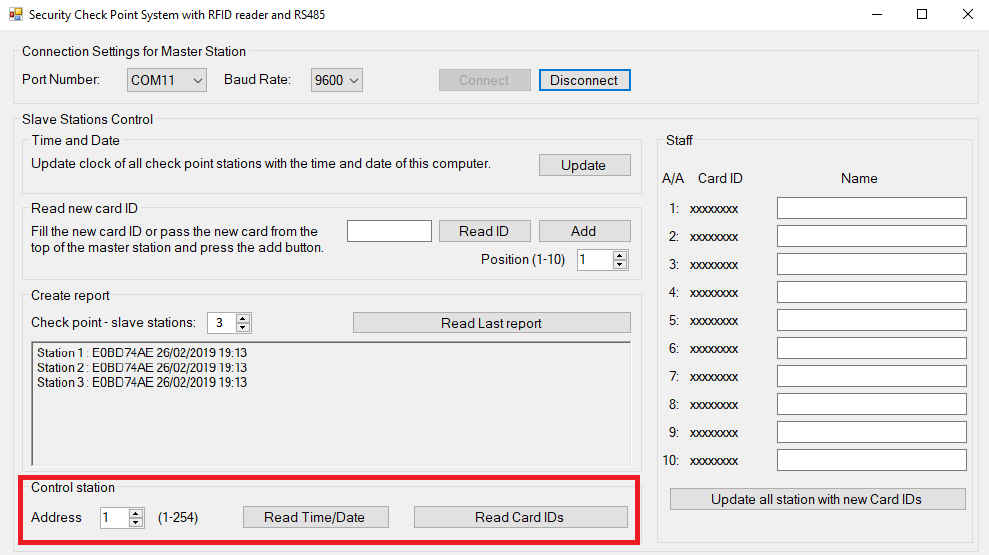
In this section we will describe the operation of the software that will run in "control" room computer.
First, you need to connect with master station via serial port.
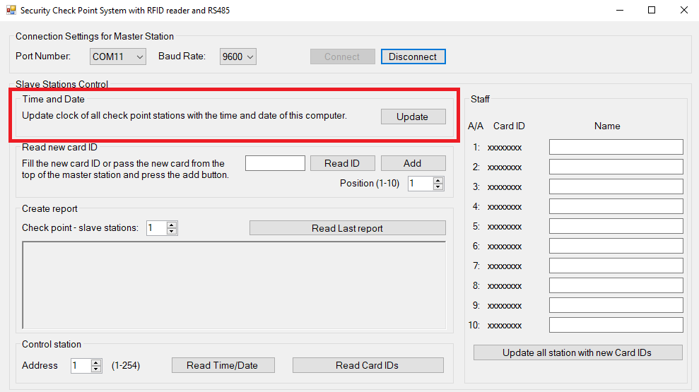
Once logged in we will update the time and date of all stations based on the clock of the computer.
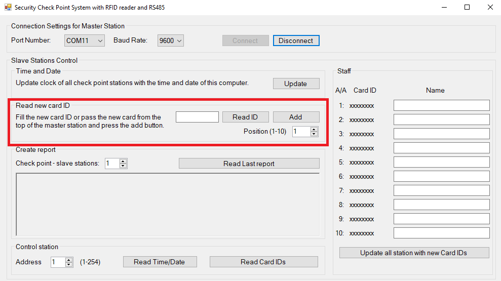
We have the option of entering the cardholder's name in our staff list. To do this, pass a card over the RFID (of master station) to read the ID and after the 'beep' sound click the "Read ID" button, select index position (from 1 to 10) and click the "Add " button. The new ID will be added to staff panel, there you can add a name of the employee. Now click on "Update Stations with Card IDs" button, now all stations are updated with new cards.
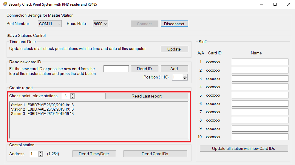
The report given by the devices since the card last passed. The total number of control stations indicates how many devices we have. We use 3 devices in our example. Clicking on the last check status report will look at the report that our devices gave us. For example: Station 1 replied that the E0 BD 74 AE card passed on 26/2/2019 at 19:13.
Finally, we can read the time and date or the card table of each device.
Well Done!
I hope you liked this, let me know in the comments!!!