Introduction
|
|
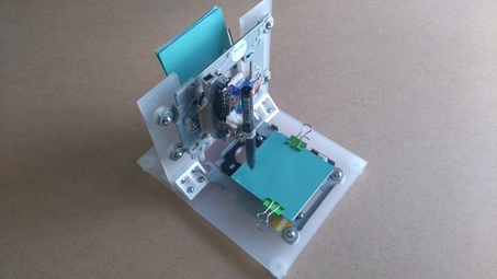
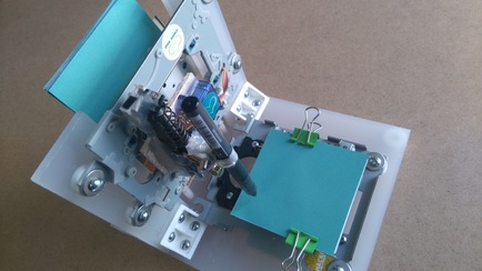
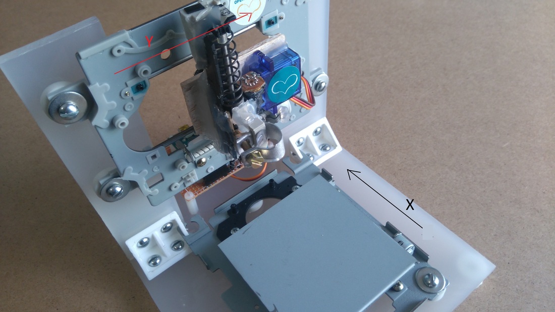
In this project I will show you how to easily build your own low-cost Arduino Mini CNC Plotter! This project is an update from my previous cnc, with better construction and with more accuracy. I decided to make this detailed guide to help you make it on a few easy steps. Small description: For the X and Y axes we will use two stepper motors and rails from dvd/cd drives and for the Z axis we will use a small servo motor that moves the pen up and down. For the mounting base we will use a small piece of plexiglass. You can easily attach a pen (or pencil) - irrespective of its thickness - on it. |
I tried to use an extension of cutting tool (e.g.Dremel) to engrave materials with no success. So this mini cnc can only be used as a small plotter and not as an engraver machine.
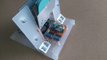
The Arduino-based circuit is using the ATmega328 microcontroller, two L293 motor driver ICs and an usb to serial module. You can easily make it with the Arduino uno board and an breadboard.
You can also use an Bluetooth module (e.g. HC-06) to print your texts (or images) wirelessly through your computer Bluetooth connection! Pretty cool huh?
Arrows may not center when in edit mode. Once site is published, the arrow will be centered on the tab
When the site is published, this border and note will not show up.
Drag & drop your tab 1 content here
|
Tip: See the images above.
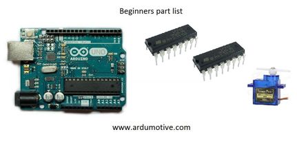
For the circuit you will need: Part list for beginners:
|
|
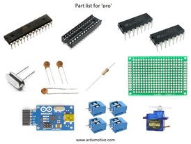
Part list for 'pro' :
**USB to Serial adapter will allow the circuit to communicate with the computer through the USB cable, just like Arduino uno does.
***Why to use screw terminal connectors? Because you don't want to solder and desolder cables from stepper motors until you find the correct working combination!
For the mounting base:
Tools:
- ATmega328p (with Arduino Bootloader)*
- 28 pin DIP IC Socket
- 16MHz Crystal Oscillator
- 2x 22pF and 1x 100nF capacitors
- 10K resistor
- USB to Serial adapter**
- 2x L293D ICs
- Mini Servo Motor
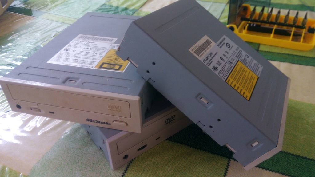
- 2x DVD/CD Drives
- Prototyping PCB Circuit Board Stripboard
- 4x 2pins Screw Terminal Connector (or 2x 4 pins Screw Terminal Connector)***
**USB to Serial adapter will allow the circuit to communicate with the computer through the USB cable, just like Arduino uno does.
***Why to use screw terminal connectors? Because you don't want to solder and desolder cables from stepper motors until you find the correct working combination!
For the mounting base:
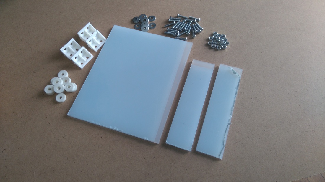
- One piece of plexiglass 20x16 cm (thickness 5mm) (for X axis)
- Two pieces of plexiglass 14x4 cm (thickness 5mm) (for Y axis)
- A few nut screws, nuts and shims (~20)
- A few spacers
- Four supporting angles (preferably plastic)
Tools:
- Screwdriver
- Soldering iron
- Solder
- Drill
- Cutting tool (e.g. Dremel) (Optional for cutting plastic/plexiglass parts)
- Glue
Drag & drop your tab 2 content here
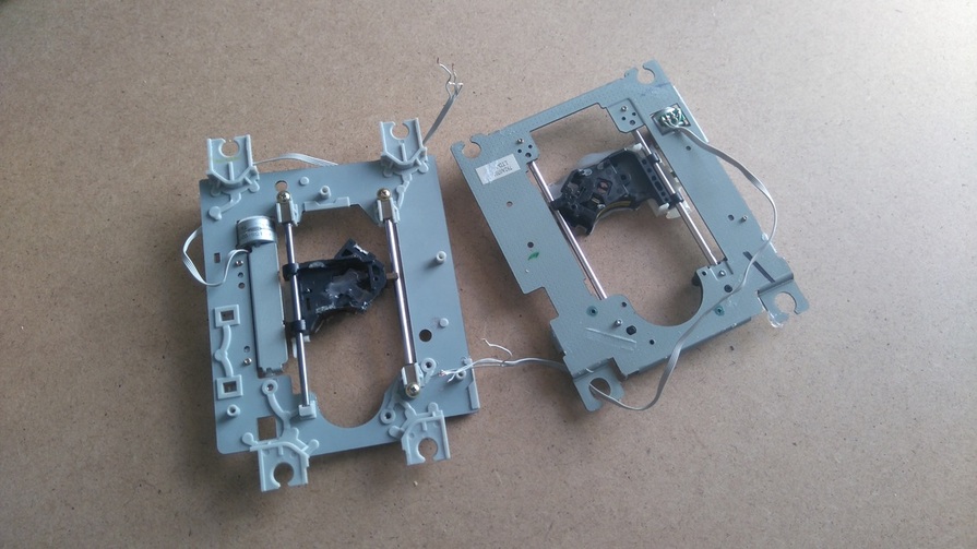
First step to start building this cnc machine is to disassemble the dvd/cd drives and take off them the stepper motors. Use the screwdriver to open and take off them the rails (see 1st image above).
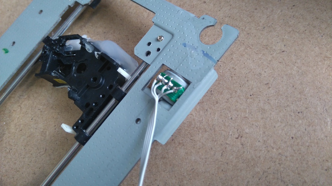
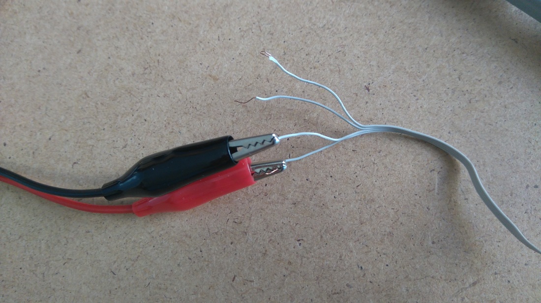
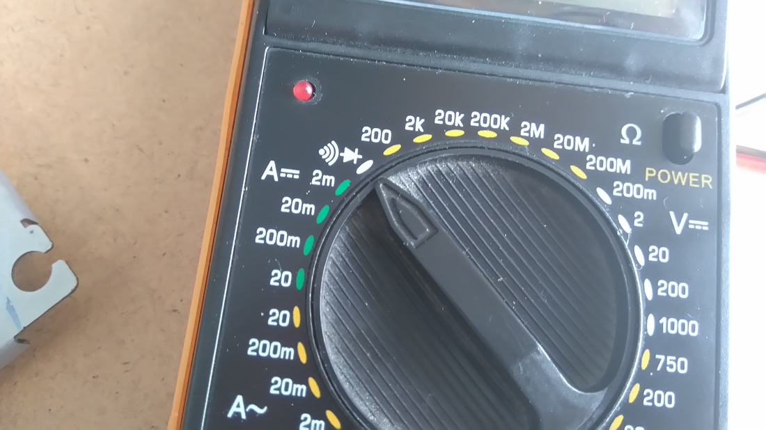
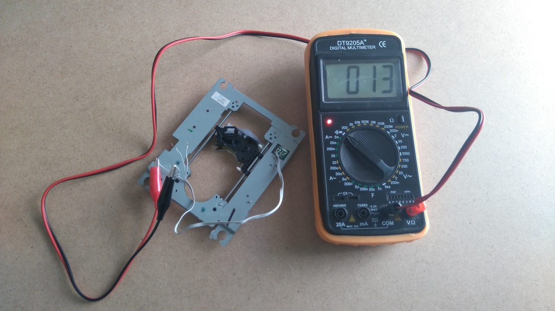
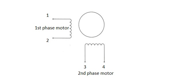
Now that we have the two stepper motors we need to solder some cables on them. Proceed with caution, see the 2nd image above. Now we need to find the correct combination to drive and use them correctly, so take a multimeter with alligator clips (3rd image) and put it on "short-circuit" function (4th image). Usually (5th image), the first and second cables are closing the circuit - the led is turned on and a beep sounds - this means that we have found the fist phase-motor of stepper motor. The other two cables, third and forth, uses the second phase-motor of stepper motor.
In my case, one of stepper motors uses the first and third cable for first phase-motor and the second and forth cable for second phase-motor.
Find the correct combination and proceed to next step.
In my case, one of stepper motors uses the first and third cable for first phase-motor and the second and forth cable for second phase-motor.
Find the correct combination and proceed to next step.
Drag & drop your tab 3 content here
Mounting base, X , Y and Z axes
Follow the steps below and see the images above
For X axis:
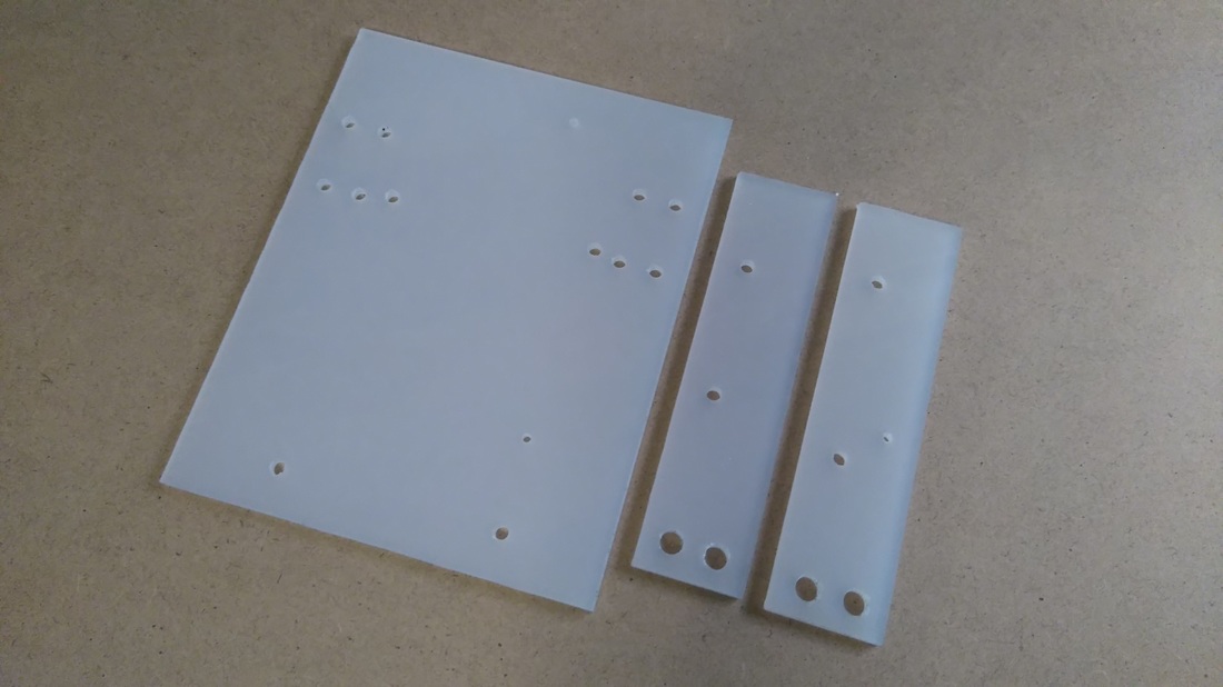
Place one stepper motor (with rails) on a big plexiglass piece and mark it with a pen in order to open the (4) holes for the screws. Make sure that is perfectly align! (use a triangle ruler). Open the holes and mount the motor with nut screws.
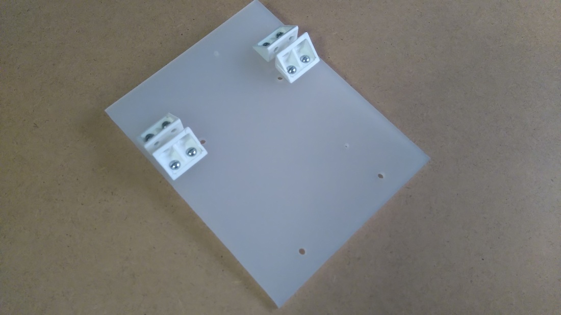
Place on one side of it the four mounting angles and then mark it with a pen in order to open the (8) holes required for the screws. Make sure that the distance between them is 5mm (thickness of plexiglass). The second image above will help you to understand more.
For Y axis:
Place the other stepper motor on two plexiglass pieces and mark them with a pen in order to open the (4) holes for the screws. Again, make sure that the motor is perfectly align (use a triangle ruler).
Place the two pieces of plexiglass on the X axis (big plexiglass piece) and mark them with a pen in order to open the (4) holes required to fit on the mounting angles.
Complete the construction:
Open all holes and complete the construction (see the 3rd and 4th image above). As you can see I placed a metal surface on X axis to fit a note-paper sheet on it. A note-paper sheet usually has dimensions 75mm x 75mm, but remember that printing area is only 40mm x 40mm. Remember, all parts must be perfectly align with others, this is very important!
For Z axis:
|
|
That's the most difficult part of our construction.
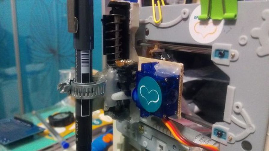
You will need something to attach it on X axis, a flat surface. On that surface you will attach the servo motor (Z axis) and the pen base. Pen (or pencil) must be able to move up and down with the help of servo motor. Watch the above image to understand what you need to do to duild Z axis. Tip! Use your imagination ;) |
Drag & drop your tab 4 content here
|
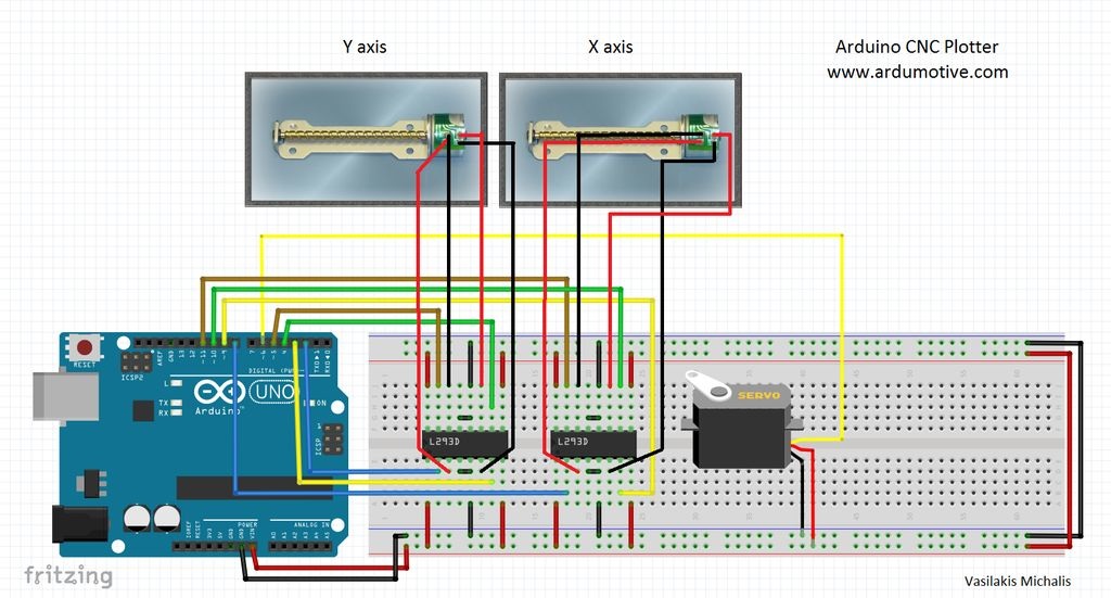
Now that we have our contraction ready, it's time to build the circuit and test the stepper motors (X and Y axis). Watch the above image with breadboard circuit schematic.
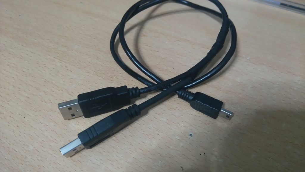
Steppers motors wiring is something that need patient. On the next step you will find a 'testing' code for x and y axes. If a stepper doesn't work properly you must find the correct working combination by changing the cables between them and the L293D ICs. Power: You will need more current than one usb port can give, so you must connect one more usb cable, see the 2nd image above. Connect only power cables (usually red and black) with the primary one. The voltage remains 5V, but you have doubled the current! (from wiki: max. current of USB 2.0: 0.5 A and of USB 3.0 & 3.1: 0.9 A). |
Note: If you want to use a different hardware (e.g. motor shield, stepper driver IC) you have to make changes on the above circuit and on the Arduino code. Sorry but I can't help you, search the web to find more info about your hardware. This guide is made for L293D IC motor driver.
Drag & drop your tab 5 content here
Testing the X and Y axis movement
Here is the testing code for X and Y axss, embedded using Codebender!
Codebender is an online Arduino IDE - It's the easiest way to program your Arduino board directly from your browser! Just click on the "Run on Arduino" button and that's it! Try it! It's really amazing!
Codebender is an online Arduino IDE - It's the easiest way to program your Arduino board directly from your browser! Just click on the "Run on Arduino" button and that's it! Try it! It's really amazing!
|
For X axis
|
For Y axis
|
If you see any movement here that means that the stepper motors wiring is correct! if you don't, try to change the cables...
The CNC Code
1 2 3 4 5 6 7 8 9 10 11 12 13 14 15 16 17 18 19 20 21 22 23 24 25 26 27 28 29 30 31 32 33 34 35 36 37 38 39 40 41 42 43 44 45 46 47 48 49 50 51 52 53 54 55 56 57 58 59 60 61 62 63 64 65 66 67 68 69 70 71 72 73 74 75 76 77 78 79 80 81 82 83 84 85 86 87 88 89 90 91 92 93 94 95 96 97 98 99 100 101 102 103 104 105 106 107 108 109 110 111 112 113 114 115 116 117 118 119 120 121 122 123 124 125 126 127 128 129 130 131 132 133 134 135 136 137 138 139 140 141 142 143 144 145 146 147 148 149 150 151 152 153 154 155 156 157 158 159 160 161 162 163 164 165 166 167 168 169 170 171 172 173 174 175 176 177 178 179 180 181 182 183 184 185 186 187 188 189 190 191 192 193 194 195 196 197 198 199 200 201 202 203 204 205 206 207 208 209 210 211 212 213 214 215 216 217 218 219 220 221 222 223 224 225 226 227 228 229 230 231 232 233 234 235 236 237 238 239 240 241 242 243 244 245 246 247 248 249 250 251 252 253 254 255 256 257 258 259 260 261 262 263 264 265 266 267 268 269 270 271 272 273 274 275 276 277 278 279 280 281 282 283 284 285 286 287 288 289 290 291 292 293 294 295 296 297 298 299 300 301 302 303 304 305 306 307 308 309 310 311 312 313 314 315 316 317 318 319 320 321 322 323 324 325 326 327 328 329 330 331 332 333 334 335 336 337 338 339 340 341 342 343 344 345 346 347 348 349 350 351 352 353 354 355 356 357 358 359 360 361 362 363 364 365 366 367 368 369 370 371 372 373 374 375 376 377 378 379 380 381 382 383 384 385 386 387 388 389 390 391 392 393 394 395 396 397 398 399 400 401 402 | /* Mini CNC Plotter firmware, based in TinyCNC https://github.com/MakerBlock/TinyCNC-Sketches Send GCODE to this Sketch using gctrl.pde https://github.com/damellis/gctrl Convert SVG to GCODE with MakerBot Unicorn plugin for Inkscape available here https://github.com/martymcguire/inkscape-unicorn More information about the Mini CNC Plotter here (german, sorry): http://www.makerblog.at/2015/02/projekt-mini-cnc-plotter-aus-alten-cddvd-laufwerken/ */ #include <Servo.h> #include <Stepper.h> #define LINE_BUFFER_LENGTH 512 // Servo position for Up and Down const int penZUp = 80; const int penZDown = 40; // Servo on PWM pin 6 const int penServoPin = 6; // Should be right for DVD steppers, but is not too important here const int stepsPerRevolution = 20; // create servo object to control a servo Servo penServo; // Initialize steppers for X- and Y-axis using this Arduino pins for the L293D H-bridge Stepper myStepperY(stepsPerRevolution, 2,3,4,5); Stepper myStepperX(stepsPerRevolution, 8,9,10,11); /* Structures, global variables */ struct point { float x; float y; float z; }; // Current position of plothead struct point actuatorPos; // Drawing settings, should be OK float StepInc = 1; int StepDelay = 0; int LineDelay = 50; int penDelay = 50; // Motor steps to go 1 millimeter. // Use test sketch to go 100 steps. Measure the length of line. // Calculate steps per mm. Enter here. float StepsPerMillimeterX = 6.0; float StepsPerMillimeterY = 6.0; // Drawing robot limits, in mm // OK to start with. Could go up to 50 mm if calibrated well. float Xmin = 0; float Xmax = 40; float Ymin = 0; float Ymax = 40; float Zmin = 0; float Zmax = 1; float Xpos = Xmin; float Ypos = Ymin; float Zpos = Zmax; // Set to true to get debug output. boolean verbose = false; // Needs to interpret // G1 for moving // G4 P300 (wait 150ms) // M300 S30 (pen down) // M300 S50 (pen up) // Discard anything with a ( // Discard any other command! /********************** * void setup() - Initialisations ***********************/ void setup() { // Setup Serial.begin( 9600 ); penServo.attach(penServoPin); penServo.write(penZUp); delay(200); // Decrease if necessary myStepperX.setSpeed(250); myStepperY.setSpeed(250); // Set & move to initial default position // TBD // Notifications!!! Serial.println("Mini CNC Plotter alive and kicking!"); Serial.print("X range is from "); Serial.print(Xmin); Serial.print(" to "); Serial.print(Xmax); Serial.println(" mm."); Serial.print("Y range is from "); Serial.print(Ymin); Serial.print(" to "); Serial.print(Ymax); Serial.println(" mm."); } /********************** * void loop() - Main loop ***********************/ void loop() { delay(200); char line[ LINE_BUFFER_LENGTH ]; char c; int lineIndex; bool lineIsComment, lineSemiColon; lineIndex = 0; lineSemiColon = false; lineIsComment = false; while (1) { // Serial reception - Mostly from Grbl, added semicolon support while ( Serial.available()>0 ) { c = Serial.read(); if (( c == '\n') || (c == '\r') ) { // End of line reached if ( lineIndex > 0 ) { // Line is complete. Then execute! line[ lineIndex ] = '\0'; // Terminate string if (verbose) { Serial.print( "Received : "); Serial.println( line ); } processIncomingLine( line, lineIndex ); lineIndex = 0; } else { // Empty or comment line. Skip block. } lineIsComment = false; lineSemiColon = false; Serial.println("ok"); } else { if ( (lineIsComment) || (lineSemiColon) ) { // Throw away all comment characters if ( c == ')' ) lineIsComment = false; // End of comment. Resume line. } else { if ( c <= ' ' ) { // Throw away whitepace and control characters } else if ( c == '/' ) { // Block delete not supported. Ignore character. } else if ( c == '(' ) { // Enable comments flag and ignore all characters until ')' or EOL. lineIsComment = true; } else if ( c == ';' ) { lineSemiColon = true; } else if ( lineIndex >= LINE_BUFFER_LENGTH-1 ) { Serial.println( "ERROR - lineBuffer overflow" ); lineIsComment = false; lineSemiColon = false; } else if ( c >= 'a' && c <= 'z' ) { // Upcase lowercase line[ lineIndex++ ] = c-'a'+'A'; } else { line[ lineIndex++ ] = c; } } } } } } void processIncomingLine( char* line, int charNB ) { int currentIndex = 0; char buffer[ 64 ]; // Hope that 64 is enough for 1 parameter struct point newPos; newPos.x = 0.0; newPos.y = 0.0; // Needs to interpret // G1 for moving // G4 P300 (wait 150ms) // G1 X60 Y30 // G1 X30 Y50 // M300 S30 (pen down) // M300 S50 (pen up) // Discard anything with a ( // Discard any other command! while( currentIndex < charNB ) { switch ( line[ currentIndex++ ] ) { // Select command, if any case 'U': penUp(); break; case 'D': penDown(); break; case 'G': buffer[0] = line[ currentIndex++ ]; // /!\ Dirty - Only works with 2 digit commands // buffer[1] = line[ currentIndex++ ]; // buffer[2] = '\0'; buffer[1] = '\0'; switch ( atoi( buffer ) ){ // Select G command case 0: // G00 & G01 - Movement or fast movement. Same here case 1: // /!\ Dirty - Suppose that X is before Y char* indexX = strchr( line+currentIndex, 'X' ); // Get X/Y position in the string (if any) char* indexY = strchr( line+currentIndex, 'Y' ); if ( indexY <= 0 ) { newPos.x = atof( indexX + 1); newPos.y = actuatorPos.y; } else if ( indexX <= 0 ) { newPos.y = atof( indexY + 1); newPos.x = actuatorPos.x; } else { newPos.y = atof( indexY + 1); indexY = '\0'; newPos.x = atof( indexX + 1); } drawLine(newPos.x, newPos.y ); // Serial.println("ok"); actuatorPos.x = newPos.x; actuatorPos.y = newPos.y; break; } break; case 'M': buffer[0] = line[ currentIndex++ ]; // /!\ Dirty - Only works with 3 digit commands buffer[1] = line[ currentIndex++ ]; buffer[2] = line[ currentIndex++ ]; buffer[3] = '\0'; switch ( atoi( buffer ) ){ case 300: { char* indexS = strchr( line+currentIndex, 'S' ); float Spos = atof( indexS + 1); // Serial.println("ok"); if (Spos == 30) { penDown(); } if (Spos == 50) { penUp(); } break; } case 114: // M114 - Repport position Serial.print( "Absolute position : X = " ); Serial.print( actuatorPos.x ); Serial.print( " - Y = " ); Serial.println( actuatorPos.y ); break; default: Serial.print( "Command not recognized : M"); Serial.println( buffer ); } } } } /********************************* * Draw a line from (x0;y0) to (x1;y1). * Bresenham algo from https://www.marginallyclever.com/blog/2013/08/how-to-build-an-2-axis-arduino-cnc-gcode-interpreter/ * int (x1;y1) : Starting coordinates * int (x2;y2) : Ending coordinates **********************************/ void drawLine(float x1, float y1) { if (verbose) { Serial.print("fx1, fy1: "); Serial.print(x1); Serial.print(","); Serial.print(y1); Serial.println(""); } // Bring instructions within limits if (x1 >= Xmax) { x1 = Xmax; } if (x1 <= Xmin) { x1 = Xmin; } if (y1 >= Ymax) { y1 = Ymax; } if (y1 <= Ymin) { y1 = Ymin; } if (verbose) { Serial.print("Xpos, Ypos: "); Serial.print(Xpos); Serial.print(","); Serial.print(Ypos); Serial.println(""); } if (verbose) { Serial.print("x1, y1: "); Serial.print(x1); Serial.print(","); Serial.print(y1); Serial.println(""); } // Convert coordinates to steps x1 = (int)(x1*StepsPerMillimeterX); y1 = (int)(y1*StepsPerMillimeterY); float x0 = Xpos; float y0 = Ypos; // Let's find out the change for the coordinates long dx = abs(x1-x0); long dy = abs(y1-y0); int sx = x0<x1 ? StepInc : -StepInc; int sy = y0<y1 ? StepInc : -StepInc; long i; long over = 0; if (dx > dy) { for (i=0; i<dx; ++i) { myStepperX.step(sx); over+=dy; if (over>=dx) { over-=dx; myStepperY.step(sy); } delay(StepDelay); } } else { for (i=0; i<dy; ++i) { myStepperY.step(sy); over+=dx; if (over>=dy) { over-=dy; myStepperX.step(sx); } delay(StepDelay); } } if (verbose) { Serial.print("dx, dy:"); Serial.print(dx); Serial.print(","); Serial.print(dy); Serial.println(""); } if (verbose) { Serial.print("Going to ("); Serial.print(x0); Serial.print(","); Serial.print(y0); Serial.println(")"); } // Delay before any next lines are submitted delay(LineDelay); // Update the positions Xpos = x1; Ypos = y1; } // Raises pen void penUp() { penServo.write(penZUp); delay(LineDelay); Zpos=Zmax; if (verbose) { Serial.println("Pen up!"); } } // Lowers pen void penDown() { penServo.write(penZDown); delay(LineDelay); Zpos=Zmin; if (verbose) { Serial.println("Pen down."); } } |
Drag & drop your tab 6 content here
The GCTRL program
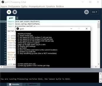
Now we are ready to print our first image! To do this we will use the gctrl.pde processing program. This program sends 'gcode' images to the cnc plotter.
What is gcode?
Gcode is a file with X,Y and Z coordinates. Header of this file is set to:
M300 S30.00 (Servo down)
G1 X10.00 Y10.00 F2500.00
G1 X20.00 Y10.00 F2500.00
M300 S50.00 (Servo up)
Download Processing from here, now donwload and open GCTRL.pde application.
What is gcode?
Gcode is a file with X,Y and Z coordinates. Header of this file is set to:
M300 S30.00 (Servo down)
G1 X10.00 Y10.00 F2500.00
G1 X20.00 Y10.00 F2500.00
M300 S50.00 (Servo up)
Download Processing from here, now donwload and open GCTRL.pde application.
You can also use Windows OS .exe files: download
- Click the "play" icon/button to start the program.
- Now press 'p' and select your Arduino serial port.
- Press 'g' and select the 'drawing.gcode' file
(If something goes wrong, press 'x' to stop the plotter)
|
|
| ||||||||||||||||||
Make your own gcode files!
To make gcode files that are compatible with this cnc machine you have to use the Inkscape.
Inkscape is professional quality vector graphics software which runs on Windows, Mac OS X and Linux. It is used by design professionals and hobbyists worldwide, for creating a wide variety of graphics such as illustrations, icons, logos, diagrams, maps and web graphics. Inkscape uses the W3C open standard SVG (Scalable Vector Graphics) as its native format, and is free and open-source software.
Download and install Inkscape from here (Important: download 0.48.5 version)
Now you need to install an Add-on that enables the export images to gcode files. This add on can be found here with installation notes.
Setup Inkscape for first use
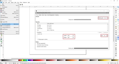
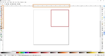
Open the Inkscape, go to File menu and click "Document Properties". See the 1st image above and make the changes, make sure to change first to "cm". Now close this window. We will use the area within 4 to 8 cm. See the 2nd image above.
|
|
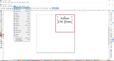
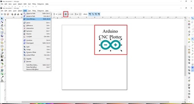
How to print text: if you want you can change font and size. Now click on cursor icon and center the text like the 3rd image above. Select Path from menu and "Object to Path". |
|
|
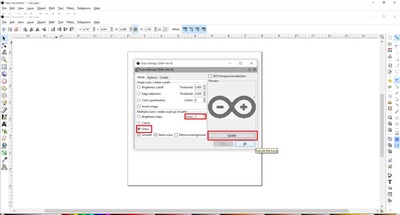
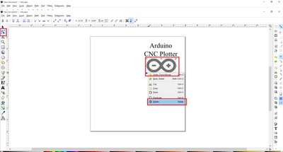
How to print image: This is more difficult than texts. Images must have a transparent background. Drag and drop your image in Inkscape. Click ok to the next window. Now you have to re-size the image to fit the printing area, see the 4th image above. Click Path from menu and "Trace Bitmap". Make changes as the 5th image above. Click ok and close the window. Now, move the gray scale image, and delete the color one behind it. Move the grey image to the correct place again and click from Path menu "Object to path". The 6th image above show how to delete image outline. |
Export as gcode
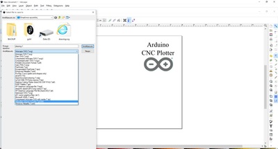
Final, go to file menu, click save as and select .gcode. Click ok on next window. That's it! Ready to go! Use the gctrl.pde app to print the gcode file on your new Arduino CNC Plotter!
Drag & drop content here

