*Σύντομα στα Ελληνικά
Introduction
In this tutorial you will learn how to use the Adafruit Pro Trinket board and how you can easily program it with Codebender!
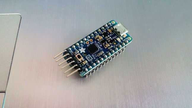
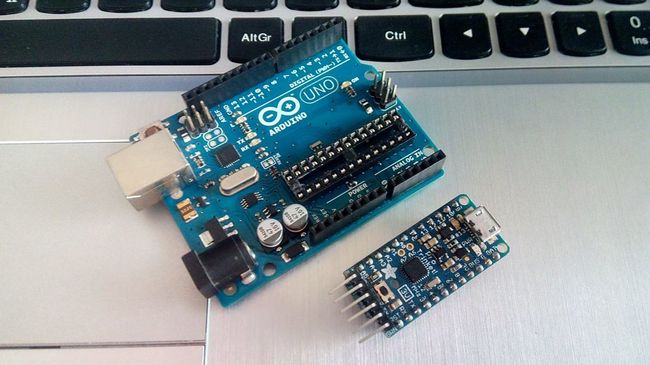
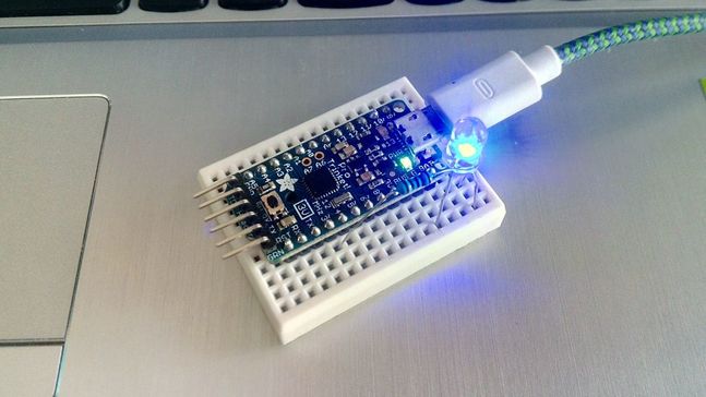
This tiny board is using the ATmega328p microcontroller, it's like an Arduino Pro Mini but with more pins and micro build-in USB port. The ATmega328p chip can also be found on Arduino uno board! It can powered up by usb cable or external battery. You can find two versions of ProTrinket board: 3V and 5V. The only diference between them is the operating 'logic' voltage.
This tiny board is using the ATmega328p microcontroller, it's like an Arduino Pro Mini but with more pins and micro build-in USB port. The ATmega328p chip can also be found on Arduino uno board! It can powered up by usb cable or external battery. You can find two versions of ProTrinket board: 3V and 5V. The only diference between them is the operating 'logic' voltage.
About the Pro Trinket board
|
Adafruit Pro Trinker Board specs:
|
|
- Power with either USB or external output (such as a battery) - it'll automatically switch over
- On-board green power LED and red LED at pin #13
- Reset button for entering the bootloader or restarting the program
- Works with 99% of existing Arduino sketches (anything that doesn't use more than 28K, and doesn't require pins #2 and #7)
- Mounting holes, you can easily attach it to breadboard or plug it in your own circuit board!
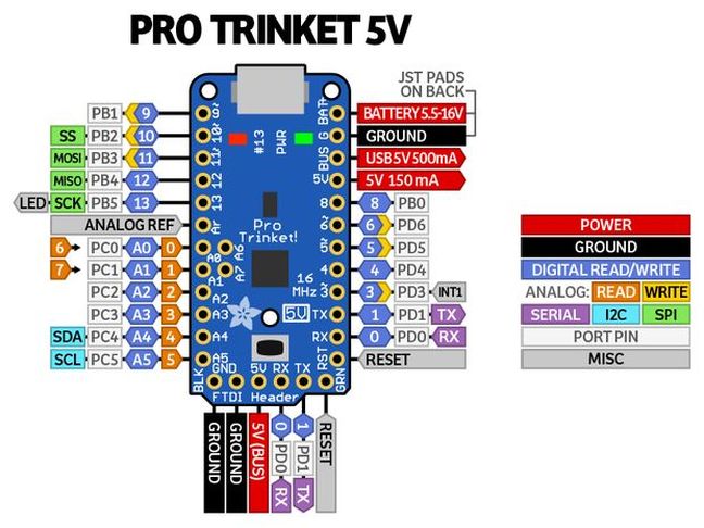
Pinout of Pro Trinket board:
- RX - also known as Digital #0, this is the hardware serial input pin
- TX - also known as Digital #1, this is the hardware serial output pin
- Digital 3 - this pin can also be used as a PWM output pin using analogWrite()
- Digital 4 - Nothing particularly special about this GPIO pin
- Digital 5 - this pin can also be used as a PWM output pin using analogWrite()
- Digital 6 - this pin can also be used as a PWM output pin using analogWrite()
- Digital 8 - Nothing particularly special about this GPIO pin
- Digital 9 - this pin can also be used as a PWM output pin using analogWrite() It's also good for driving servos because its a high-speed PWM output
- Digital 10 - this pin can also be used as a PWM output pin using analogWrite() It's also good for driving servos because its a high-speed PWM output
- Digital 11 - Also known as the SPI MOSI pin. this pin can also be used as a PWM output pin using analogWrite()
- Digital 12 - Also known as the SPI MISO pinDigital 13 - Also known as the SPI CLOCK pin
- Analog 0 - also known as Digital 14, this pin can be a digital I/O pin or an analog input pin
- Analog 1 - also known as Digital 15, this pin can be a digital I/O pin or an analog input pin
- Analog 2 - also known as Digital 16, this pin can be a digital I/O pin or an analog input pin
- Analog 3 - also known as Digital 17, this pin can be a digital I/O pin or an analog input pin
- Analog 4 - also known as Digital 18, this pin can be a digital I/O pin or an analog input pin. It's also the I2C SDA pin
- Analog 5 - also known as Digital 19, this pin can be a digital I/O pin or an analog input pin. It's also the I2C SCL pin
|
|
If you're used to using an Arduino Uno, you may notice that pins #2 and #7 are not available. That's because we use those two pins for the USB bootloader. They are not available for use and are not broken out. |
Logic Level:
There are two versions of the Pro Trinket: 3V and 5V. They are almost identical but there are slight differences in the pinouts: one has a 3V output pin in the top right, the other has a 5V output pin instead.
On a 3V Pro Trinket, the GPIO are 3.3V output level, and should not be used with 5V inputs. On a 5V Pro Trinket, the GPIO are 5V output level, and can be used with 3V inputs but may damage electronic devices that are 3V input only!
- Aref pin - this is the optional analog reference pin for the analog converter, to be used when you want the 'top' of the analog converter to be different than 3V or 5V. Connect this to your desired reference voltage (between 0 and the Pro Trinket voltage) and useanalogReference(EXTERNAL)
First time of using it?
If this is the first time you are using the Codebender or the Trinket board with your computer, click here and follow the guide to install the browser plugin and the Arduino drivers.
You should see the green power LED lit and the red bootloading LED pulse indicating that the Trinket is ready to start bootloading. If you've programmed the Pro Trinket since getting it, you can always get it back to the bootloader state by pressing the small onboard reset button.
You should see the green power LED lit and the red bootloading LED pulse indicating that the Trinket is ready to start bootloading. If you've programmed the Pro Trinket since getting it, you can always get it back to the bootloader state by pressing the small onboard reset button.
Note: If you are using Windows 10 (or something goes wrong with drivers installation for this device):
Click here and download the zip file by clicking the green box "Download Signed Adafruit Trinket/Gemma Driver".
Unzip files and then plug in the Trinket with the USB cable to start the process.
Now you have to go on Device manager, find Other devices, double click on Trinket, "Update Driver Software" and then click on "Browse my computer for driver software". Find the folder that you have unzip the drives package and click next and install.
If you find any problems with this procedure you can read this detailed guide at official Adafruit website.
Program it with Codebender!
Now we can write our first program for Pro Trinket board!
We will use the Codebender to program the board but if you still want to use the Arduino IDE you have to install Adafruit boards on it first. Just follow the instructions on this link.
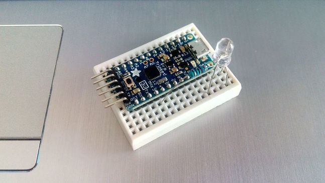
To build the circuit, connect one end of 220Ω resistor to Pro Trinket pin 3, then connect the long leg of the LED (the positive leg, called the anode) to the other end of the resistor. Now connect the short leg of the LED (the negative leg, called the cathode) to the Pro Trinket 'G' pin (GND).
|
|
Connect the Pro Trinket board with your computer, select yours Adafruit Pro Trinket version board from boards menu and leave as it port selection. Now click the "Run on Arduino" button. That's it, you've programmed your Pro Trinket board with blink sketch! You will see your LED blinking every 3 seconds.
|
If something goes wrong, press the reset button and then the "Run on Arduino" button
Update: Chrome support for Gemma/Trinket changed in November 2015, so if it doesn't work, try Firefox
You can keep playing with that by clicking the "Edit" button and start making your own modifications to the code. For example you can add a second led or change the delay time.
Well done!
You have successfully completed one more "How to" tutorial and you learned how to use the Adafruit Pro Trinket board with Codebender.
I hope you liked this, let me know in the comments.
I hope you liked this, let me know in the comments.


