|
Available Languages
|

|

|
Introduction |
Published date: 28/05/2016
|
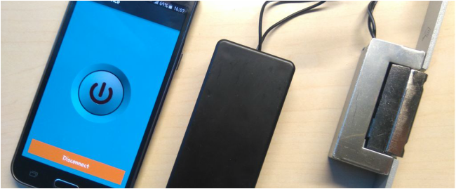
Hello! In this guide I will show you how to make your own Bluetooth controlled unlock door system by using the Arduino uno board. I made my own circuit by using the ATmega328 micro controller but this is an optional step. In this guide I will help you to make it easily on breadboard by using the Arduino uno board, and I will give you some extra tips on how you can make your own Arduino-based custom circuit.
By using this system you will be able to unlock a door for 3 seconds. After 3 seconds the electrical door opener will be automatically be locked. You can unlock it by pressing a button from the Android application that you will have in your smartphone. You have just to add your BT module in your Android phone (or tablet). In this guide we will also change the default code "1234" for safety reasons. It also has a buzzer for making a tone during unlock time.
Watch the operation video:
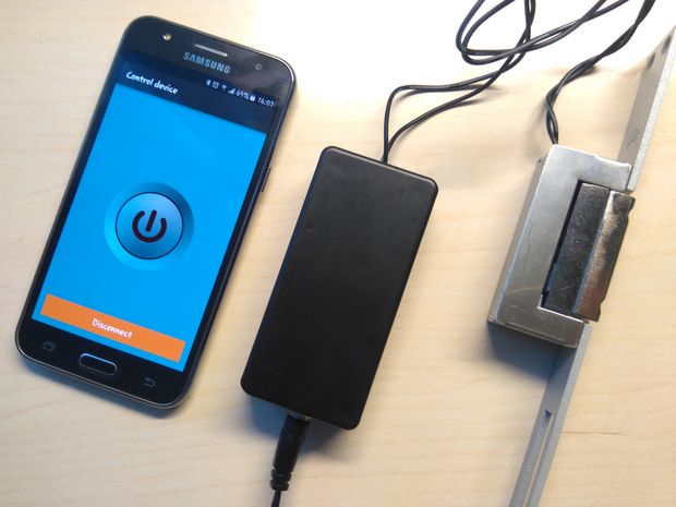
The electrical door opener that I used need 9 to 12V to operate. So for this system I used an 12V power adapter. As current passes through it, the electric lock remains open. Otherwise it remains closed.
This device was made only for educational and presentational purpose reasons, please don't use it in your home's door. But you can use it in the main door of your apartment building.
Let's get started!
This device was made only for educational and presentational purpose reasons, please don't use it in your home's door. But you can use it in the main door of your apartment building.
Let's get started!
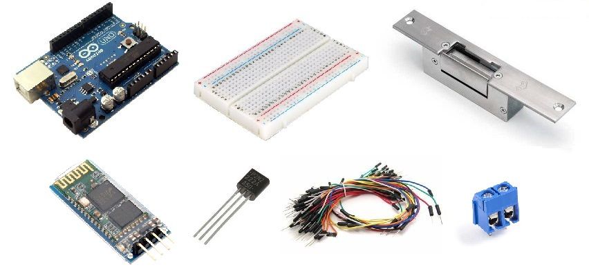
What you will need - Hardware
|
For this project you will need:
|
|
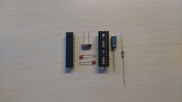
(ONLY) If you want to make your own custom - Arduino based - circuit you willalso need:
- DIP socket for atmega328
- LM7805 Voltage regulator (5V output)
- 16Mhz crystal osc
- 2x 22pF ceramic, 2x 0.22uF electrolytic capacitors
- 1x 10K resistor
- DC power jack
- pcb prototyping board
|
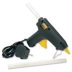
Tools:
|
|
Change BT Password
|
|
Change the default name and password of the HC-06 BT module:
Step 1: Upload the blink sketch in the Arduino uno board.
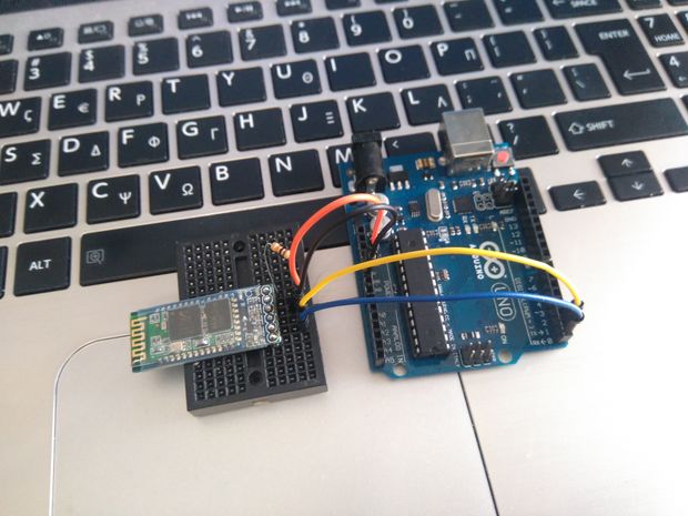
Step 2: Make the connections:
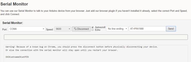
Step 3: Press the connect button on the serial monitor below (9600bps, No line ending) and type:
Step 1: Upload the blink sketch in the Arduino uno board.
Step 2: Make the connections:
- BT Vcc pin with Arduino 5V pin
- BT GND pin with Arduino GND pin
- BT RX pin with Arduino RX pin
- BT TX pin with Arduino TX pin
- Wake (or key) pin with 10k resistor to Arduino 5V pin (or BT Vcc)
Step 3: Press the connect button on the serial monitor below (9600bps, No line ending) and type:
- AT - You will see ok
- AT+NAMEMydoor - You will see OKsetname, the name of bt changed to "MyDoor"
- AT+PIN1988 - You will see OKsetpin, the password of bt changed to "1988"
Step 4: Unplug your Arduino from the usb port and proceed to the next step
The Circuit
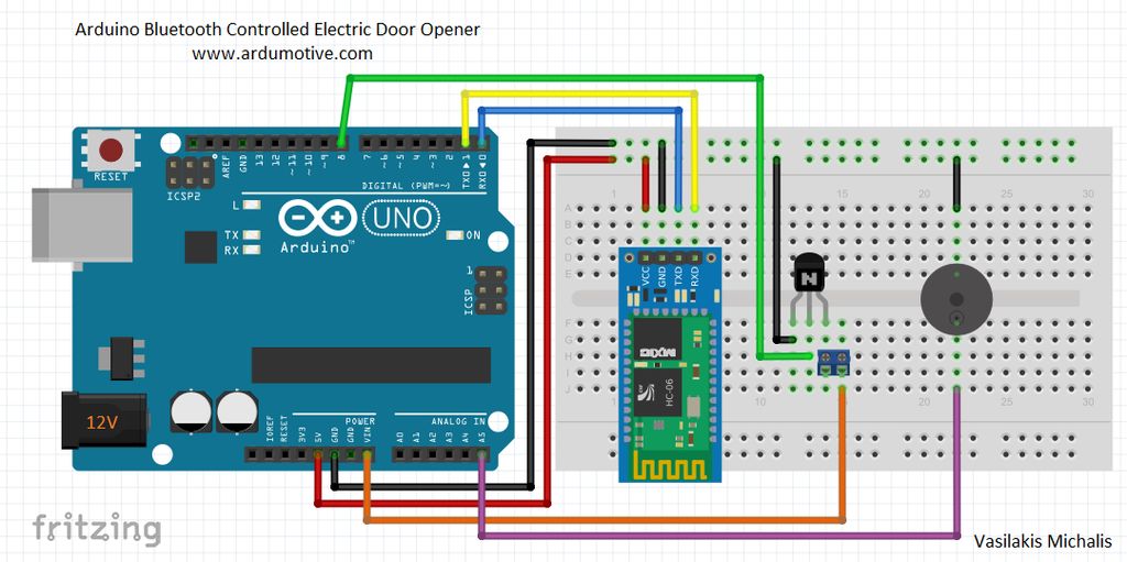
The connections are pretty easy, see the above image with the breadboard circuit schematic.
|
BT HC-06:
|
|
The Code

Here's the code, embedded using Codebender!
|
|
Try downloading the Codebender plugin and clicking on the "Run on Arduino" button to program your Arduino board with this sketch. And that's it, you've programmed your Arduino board directly from your browser! It's really amazing.
|
- Step 1: Remove RX and TX cables from the Arduino uno board
- Step 2: Connect your Arduino board with one usb port
- Step 3: Click on the "Run on Arduino" green button to program your Arduino with this sketch. And that's it, you've programmed your Arduino board! If you want to make any changes in the code below just click the "Edit" button.
- Step 4 : Connect the RX and TX cables again with the Arduino uno board
Android application
|
|
|
Download the apk file in your Android phone or table
|
| ||
You can use this application on android smartphone or tablet with Bluetooth support.
(make sure that you have already enabled the "unknown sources" from security settings to install this apk)
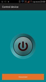
How to use it:
(make sure that you have already enabled the "unknown sources" from security settings to install this apk)
How to use it:
- Enable Bluetooth connection from settings
- Scan for devices and make a connection with "MyDoor" (pass:1988)
- Pair device
- Open app and click on "Load Paired Devices" button
- Now click to yours
Make your own custom Arduino - based circuit
|
|
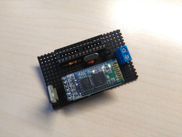
Now that you have successfully test your new project with the Arduino uno board, you can start making your own Arduino-based custom circuit! The procedure it's easy, but you will need some extras skills for making it.
So, I will try to give you some tips here to try it out by yourself:
So, I will try to give you some tips here to try it out by yourself:
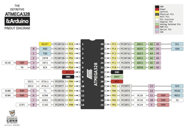
- 10K resistor must be connected between 1st (reset) pin and 7th (Vcc) of the Atmega328 micro controller.
- 16MHz crystal oscillator must be connected at pins 9 and 10, labeled as XTAL1 and XTAL2
- Connect to each pin of oscillator one 22pF capacitor. The other pin of capacitors goes to pin 8 (GND) of micro controller.
- Remember to connect the second power line of the ATmega328 with your power source, pins 20-Vcc and 22-GND.
- All other information for the Arduino pinout can be found at the second image above.
- Use the LM7805 with two 0.22uF electrolytic capacitors (on input and output pins) to take 5V from your 12V power source. This is important! Do not provide more than 6V on your custom circuit!!! It will burn your Atmega micro controller and lcd circuit.
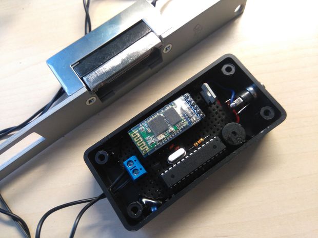
Put it in a box
|
|
Take your time and configure your box to fit your circuit.
You can make it as big (or small) you want.
You can make it as big (or small) you want.
Well done!
|
That's it! You have successfully completed this guide and now you have your own Arduino Bluetooth controller door unlock system!
I hope you liked this, let me know in the comments! |