
|
Available Languages
|

|

|
Introduction
|
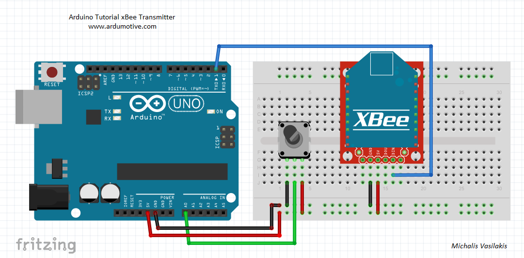
In this tutorial we will use two xBee (series 1) modules with the Arduino uno board. We will configure them to act as a receiver and transmitter to control the brightness of an LED wirelessly by using one potentiometer. |
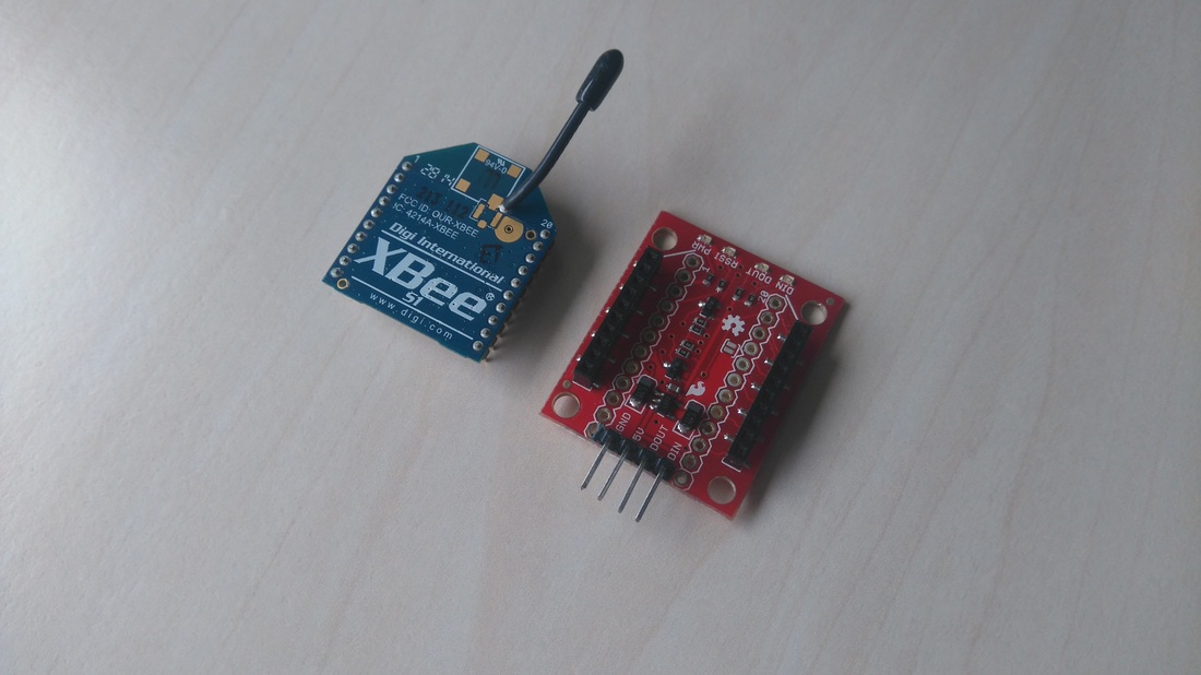
The xBee - series 1 - modules take the 802.15.4 stack (the basis for Zigbee) and wrap it into a simple to use serial command set. These modules allow a very reliable and simple communication between micro controllers, computers or other systems by using just a serial port!
They can communicate up to 300 Ft (~100m), have 2.4GHz frequency, use the 802.15.4 protocol and have data rate up to 250kbps. They have also a 1mW wire antenna on them. They supports Point to point and multi-point networks.
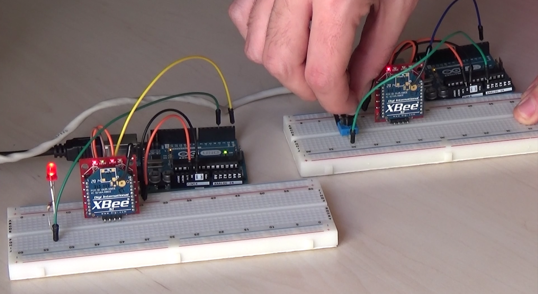
You can see the result of this tutorial on the below video :
They can communicate up to 300 Ft (~100m), have 2.4GHz frequency, use the 802.15.4 protocol and have data rate up to 250kbps. They have also a 1mW wire antenna on them. They supports Point to point and multi-point networks.
You can see the result of this tutorial on the below video :
|
|
|
Let's get started!
What you will need - Hardware
|
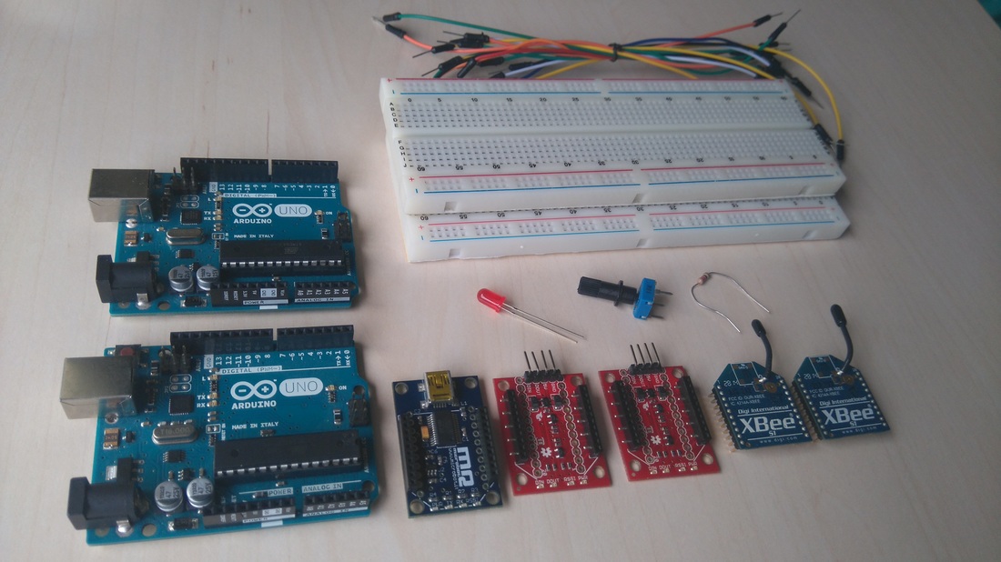
For this tutorial you will need:
|
|
XCTU - Setup your xBee modules
Download the XCTU software from here.
Run the program and connect the XBee Explorer USB board with your computer.
Click on the "Discover devices" icon to add your xBee in the XCTU software.
Run the program and connect the XBee Explorer USB board with your computer.
Click on the "Discover devices" icon to add your xBee in the XCTU software.
|
|
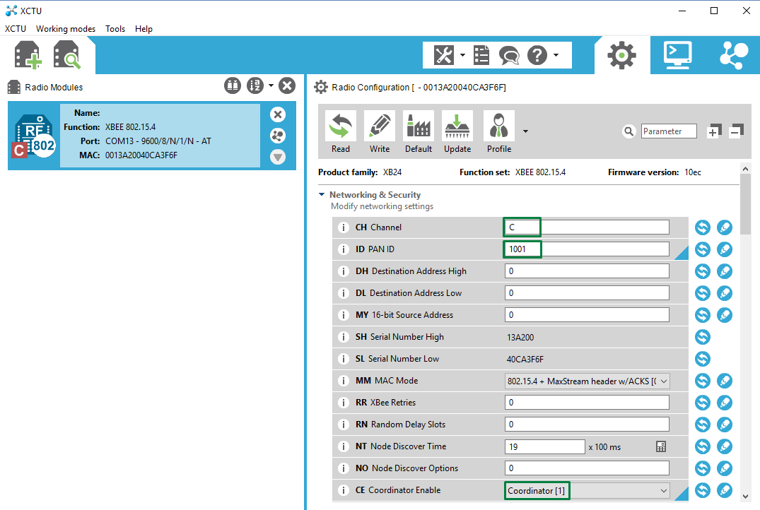
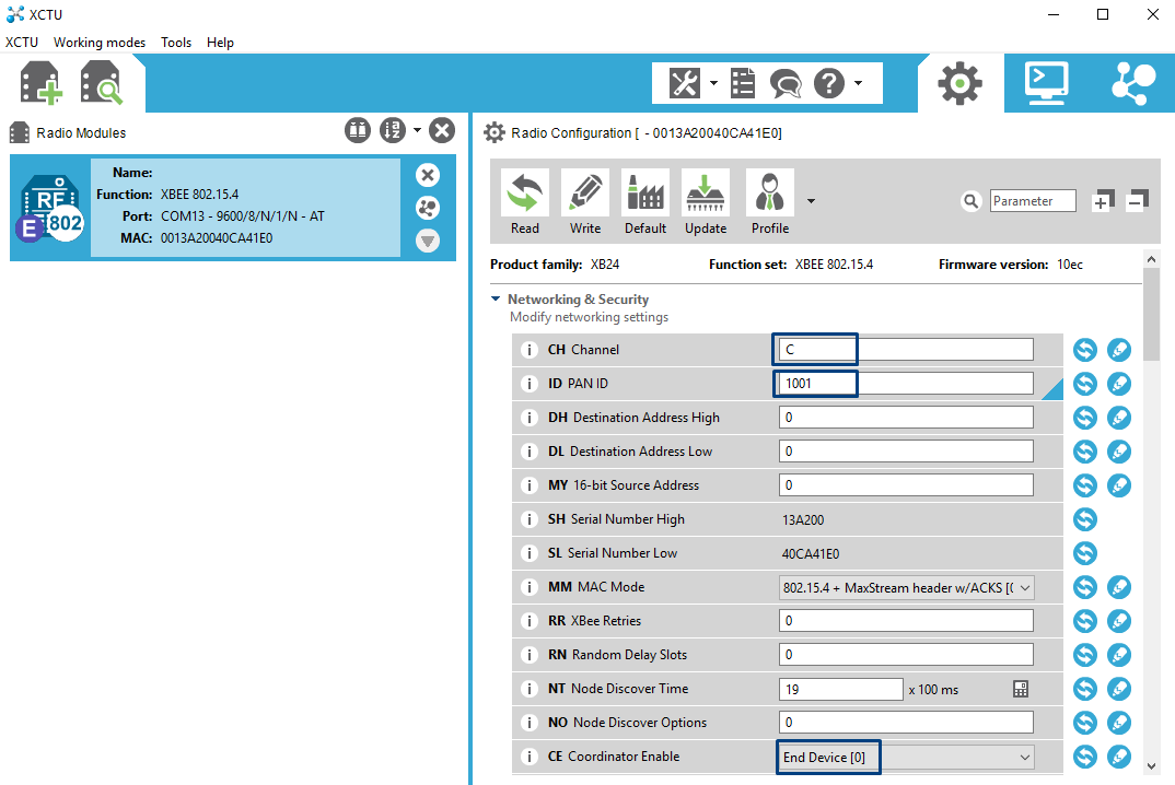
Now click on it (first image above) and set the CH field to e.g. "C" and the ID field to e.g. "1001". These values must be the same to all xBee modules to communicate with each other. Now as this xBee will be our transmitter, set the CE field as "Coordinator". If the baud rate isn't set to 9600bps, change it to this value.
Now click the "Write" button to save the changes in your xBee module.
Disconnect the xBee explorer board from your computer and connect the other xBee module on it.
Connect the explorer board with your computer again and follow the same procedure (second image above) but this time set the CE field as "End device".
Finally the configuration for our xBees must be:
|
For xBee transmitter:
CH: C
|
|

The code
Here’s the "xBee Transmitter" code.
1 2 3 4 5 6 7 8 9 10 11 12 13 14 15 16 17 18 19 20 21 22 23 24 25 26 27 28 29 | /* ~ Simple Arduino - xBee Transmitter sketch ~ Read an analog value from potentiometer, then convert it to PWM and finally send it through serial port to xBee. The xBee serial module will send it to another xBee (resiver) and an Arduino will turn on (fade) an LED. The sending message starts with '<' and closes with '>' symbol. Dev: Michalis Vasilakis // Date:2/3/2016 // Info: www.ardumotive.com // Licence: CC BY-NC-SA */ //Constants: const int potPin = A0; //Pot at Arduino A0 pin //Variables: int value ; //Value from pot void setup() { //Start the serial communication Serial.begin(9600); //Baud rate must be the same as is on xBee module } void loop() { //Read the analog value from pot and store it to "value" variable value = analogRead(A0); //Map the analog value to pwm value value = map (value, 0, 1023, 0, 255); //Send the message: Serial.print('<'); //Starting symbol Serial.print(value);//Value from 0 to 255 Serial.println('>');//Ending symbol } |
| xbeetransmiter_tutorial.zip |
And here's the "xbee Receiver" code, connect the second Arduino uno board and program it with this code.
1 2 3 4 5 6 7 8 9 10 11 12 13 14 15 16 17 18 19 20 21 22 23 24 25 26 27 28 29 30 31 32 33 34 35 36 37 38 39 40 41 42 43 44 45 46 47 48 49 50 51 52 53 54 55 56 57 58 59 60 61 62 63 64 | /* ~ Simple Arduino - xBee Receiver sketch ~ Read an PWM value from Arduino Transmitter to fade an LED The receiving message starts with '<' and closes with '>' symbol. Dev: Michalis Vasilakis // Date:2/3/2016 // Info: www.ardumotive.com // Licence: CC BY-NC-SA */ //Constants const int ledPin = 3; //Led to Arduino pin 3 (PWM) //Variables bool started= false;//True: Message is strated bool ended = false;//True: Message is finished char incomingByte ; //Variable to store the incoming byte char msg[3]; //Message - array from 0 to 2 (3 values - PWM - e.g. 240) byte index; //Index of array void setup() { //Start the serial communication Serial.begin(9600); //Baud rate must be the same as is on xBee module pinMode(ledPin, OUTPUT); } void loop() { while (Serial.available()>0){ //Read the incoming byte incomingByte = Serial.read(); //Start the message when the '<' symbol is received if(incomingByte == '<') { started = true; index = 0; msg[index] = '\0'; // Throw away any incomplete packet } //End the message when the '>' symbol is received else if(incomingByte == '>') { ended = true; break; // Done reading - exit from while loop! } //Read the message! else { if(index < 4) // Make sure there is room { msg[index] = incomingByte; // Add char to array index++; msg[index] = '\0'; // Add NULL to end } } } if(started && ended) { int value = atoi(msg); analogWrite(ledPin, value); //Serial.println(value); //Only for debugging index = 0; msg[index] = '\0'; started = false; ended = false; } } |
| xbeereceiver_tutorial.zip |
The Circuit
|
|
|
[object Object]
|
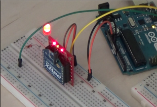
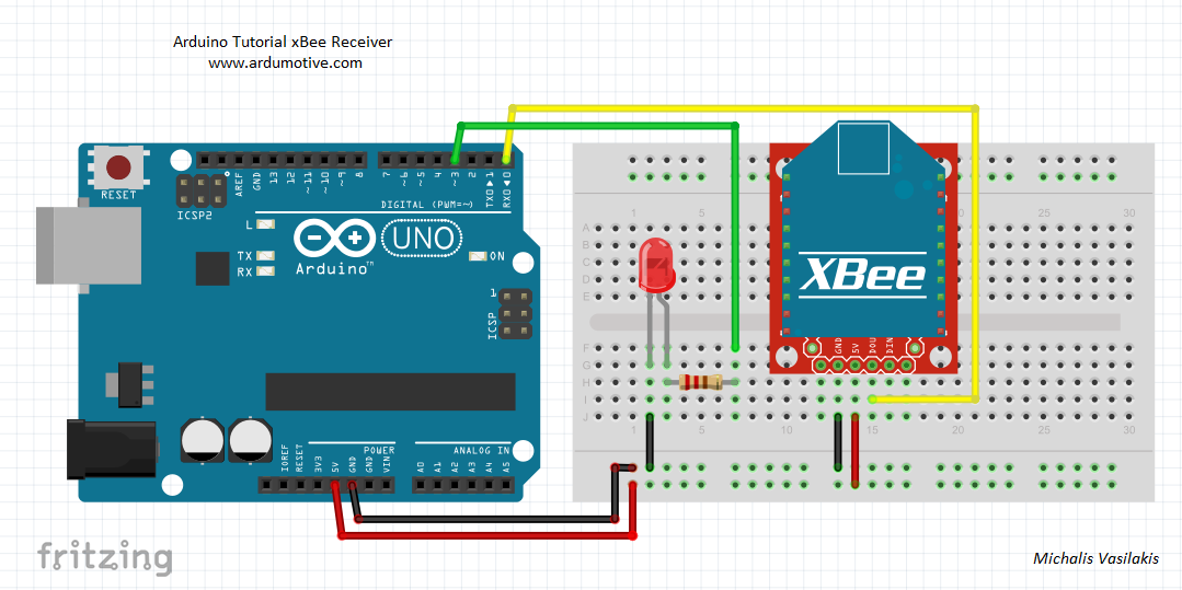
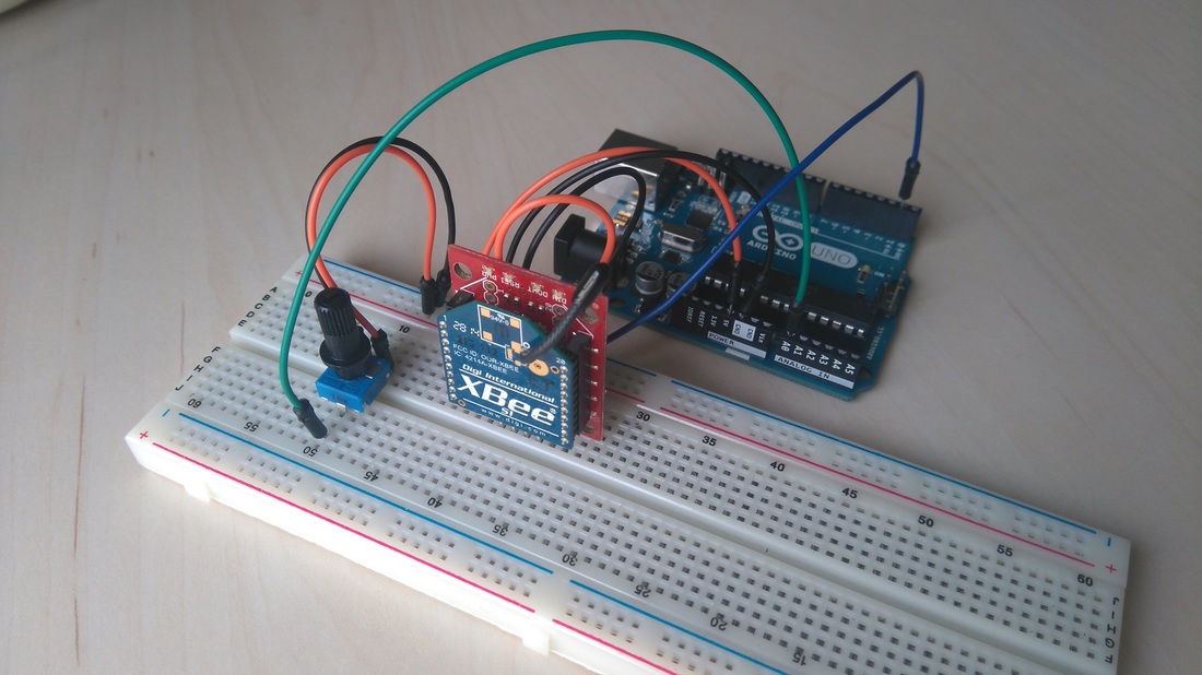
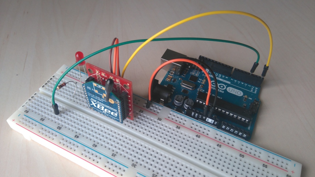
The connections are pretty easy, see the above image with the breadboard circuit schematics.
Power on both Arduino uno boards and try to fade the led by turning the potentiometer. |
|
|
Well done!
You have successfully completed one more "How to" tutorial and you learned how to fade an LED wirelessly by using the xBee S1 modules.
I hope you liked this, let me know in the comments.
I hope you liked this, let me know in the comments.