Introduction
|
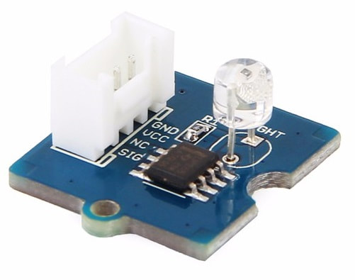
The Grove - Light sensor integrates a photo-resistor(light dependent resistor) to detect the intensity of light. The resistance of photo-resistor decreases when the intensity of light increases. A dual OpAmp chip LM358 on board produces voltage corresponding to intensity of light(i.e. based on resistance value). The output signal is analog value, the brighter the light is, the larger the value.
This module can be used to build a light controlled switch i.e. switch off lights during day time and switch on lights during night time. |
What we need and connection
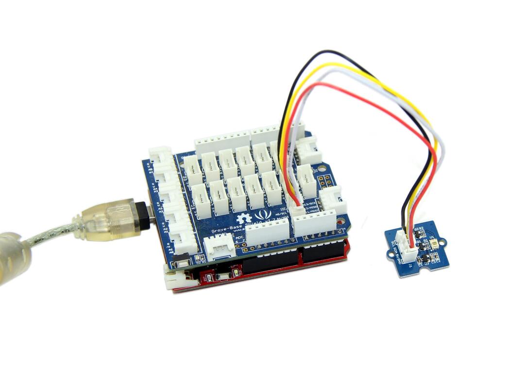
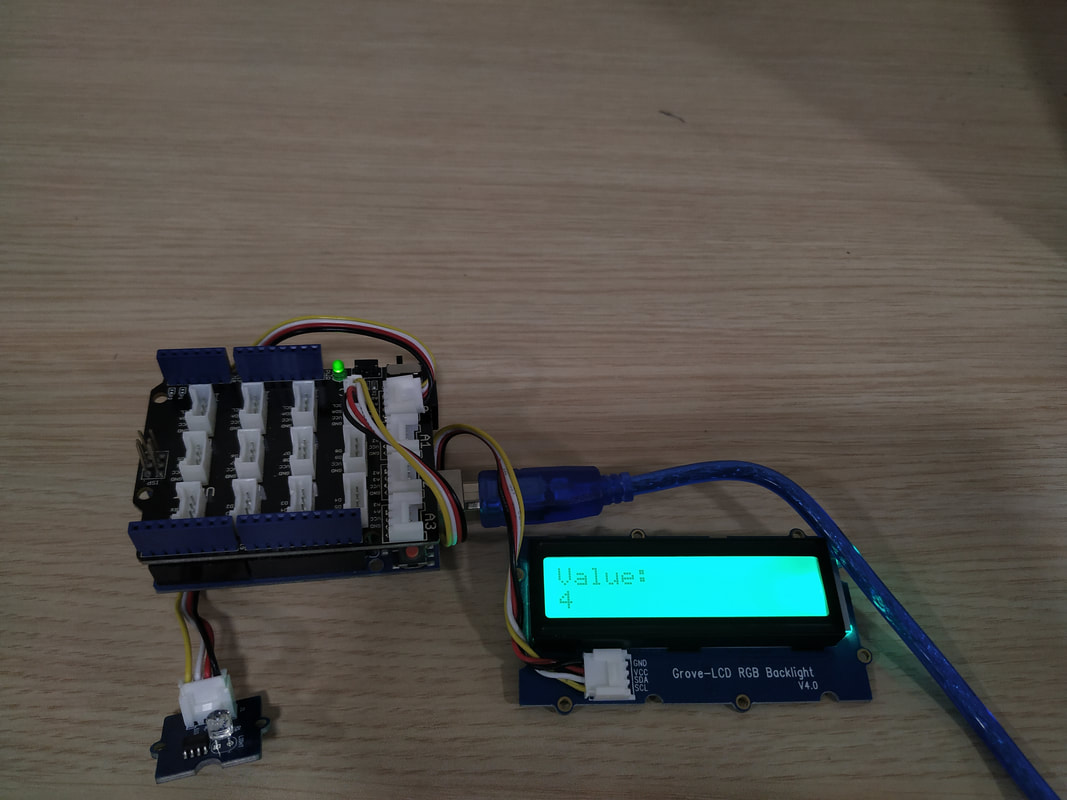
For this tutorial we will need:
- Arduino UNO
- Grove Base Shield
- Light Sensor
- LCD RGB Backlight (Connect Grove-LCD RGB Backlight to port I2C of Grove-Base Shield)
The code
1 2 3 4 5 6 7 8 9 10 11 12 13 14 15 16 17 18 19 20 21 22 23 24 25 26 27 28 29 30 31 32 | #include <Wire.h> #include "rgb_lcd.h" rgb_lcd lcd; const int colorR = 0; const int colorG = 250; const int colorB = 0; void setup() { // set up the LCD's number of columns and rows: lcd.begin(16, 2); lcd.setRGB(colorR, colorG, colorB); // Print a message to the LCD. lcd.print("Hello Ardumotive"); delay(1500); } void loop() { int value = analogRead(A0); value = map(value, 0, 800, 0, 10); lcd.clear(); lcd.setCursor(0,0); lcd.print("Value: "); lcd.setCursor(0,1); lcd.print(value); delay(1000); } |
|
Download the code from here and open it with Arduino IDE. Libraries are also inside the ZIP file.
|
| ||||||
Well done!
You have successfully completed one more Arduino Grove tutorial.
I hope you liked this, let me know in the comments.
I hope you liked this, let me know in the comments.


