|
Available Languages
|

|

|
Introduction |
Published date: 03/05/2016
|

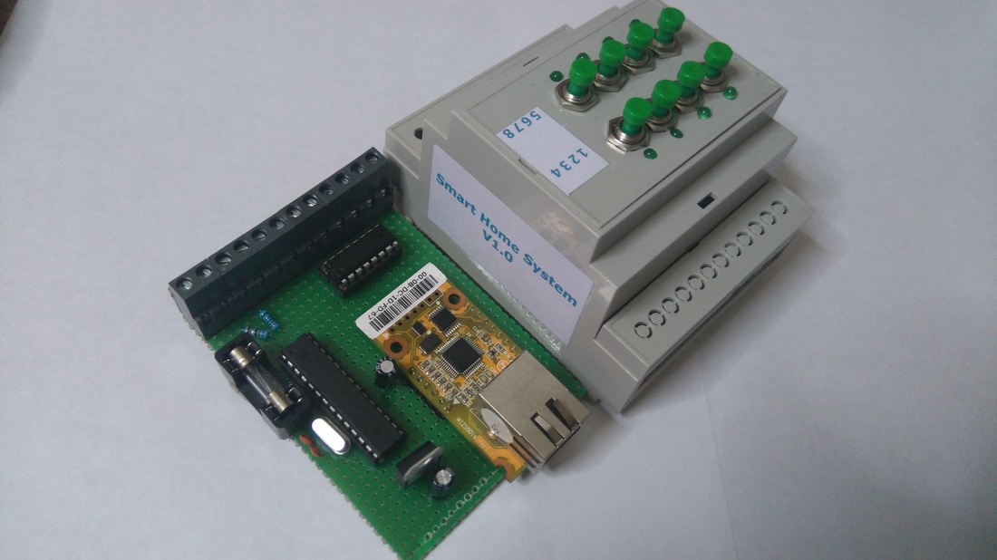
In this guide I will show you how you can easily make your own smart home system based on Arduino uno and an Ethernet module (or shield).
You will be able to use this system from any device (mobile phone, pc, tablet) because the user interface (1st image) is accessible through a browser window. Because of that, it supports all operating systems! You can also control your electrical device from your local area network and (or) from your internet worldwide connection. So, it can be accessible from anywhere! But, this also means that it can be controlled from anyone, so before you make it accessible through your internet connection, consider adding security measures to protect your IOT system.
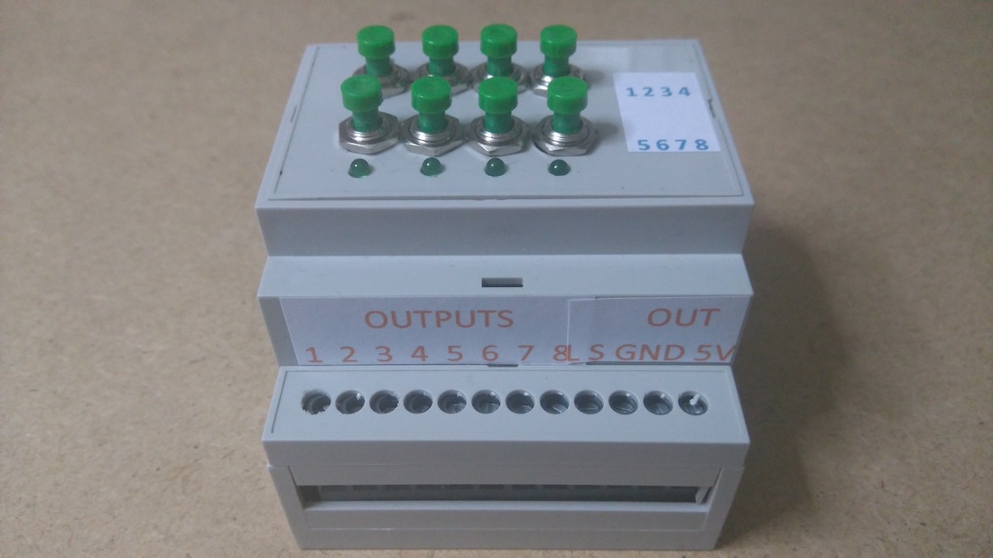
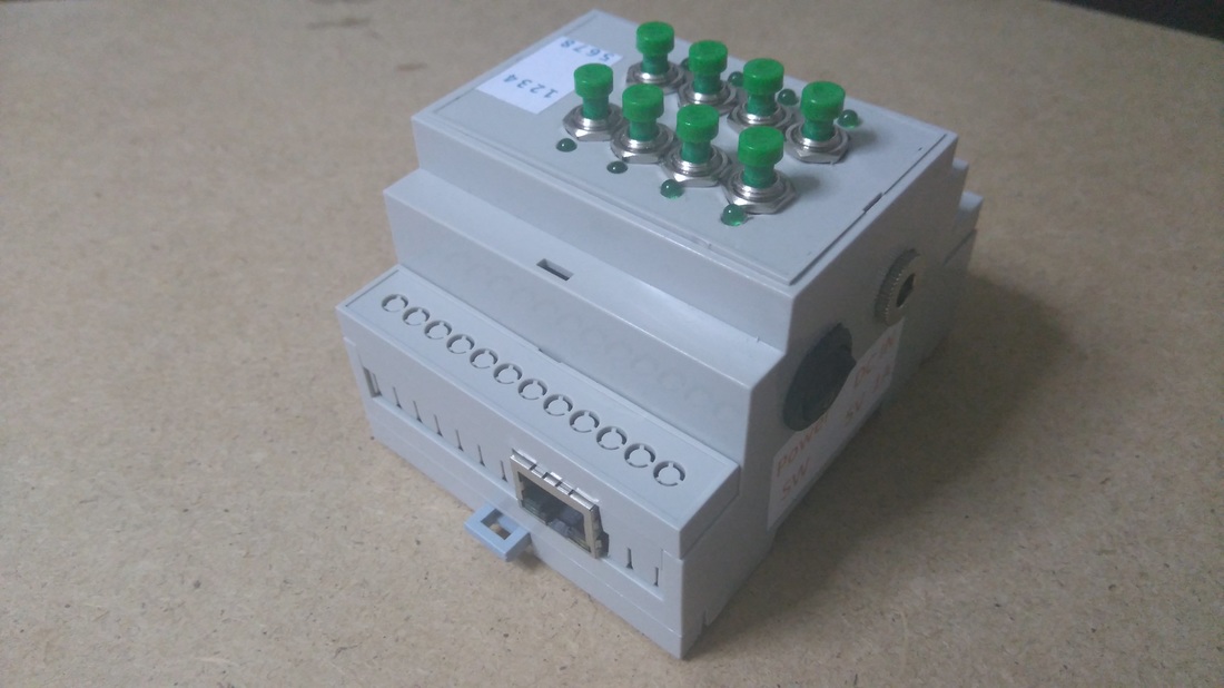
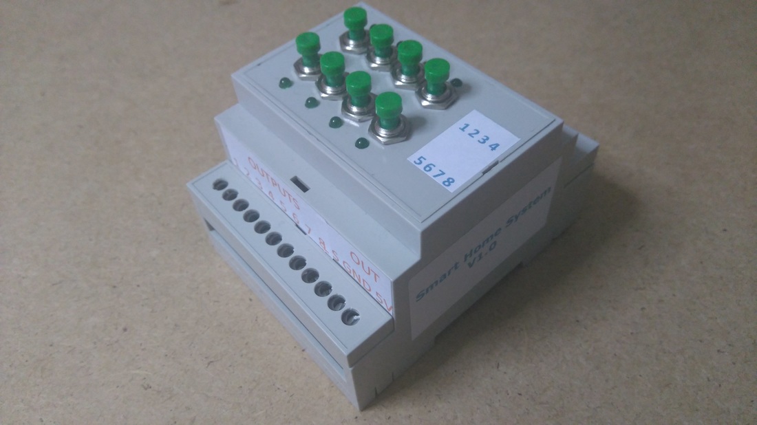
It supports up to seven +1 outputs for controlling any electrical device in your home. The 8th output can be connected with a photocell to automatically control an outside light (or lamp). These 8 outputs can be expanded to support more output channels. It also has an LED on every output channel and a button to control it manually. Every output channel can be connected with a relay switch or connected to an RF device to control a relay wirelessly. It has a power output (5V up to 1A) for powering up any relay board or other external device.
It can be powered from a 5V up to 1A power adapter, even from your usb 3.0 computer port. If you want to power it up with a different voltage power adapter consider adding a 5V voltage regulator to your circuit.
The hole project cost me less than $40! It's really easy to make it!!!
Please read and agree with license Attribution - NonCommercial - ShareAlike.
Let's get started!
You will be able to use this system from any device (mobile phone, pc, tablet) because the user interface (1st image) is accessible through a browser window. Because of that, it supports all operating systems! You can also control your electrical device from your local area network and (or) from your internet worldwide connection. So, it can be accessible from anywhere! But, this also means that it can be controlled from anyone, so before you make it accessible through your internet connection, consider adding security measures to protect your IOT system.
It supports up to seven +1 outputs for controlling any electrical device in your home. The 8th output can be connected with a photocell to automatically control an outside light (or lamp). These 8 outputs can be expanded to support more output channels. It also has an LED on every output channel and a button to control it manually. Every output channel can be connected with a relay switch or connected to an RF device to control a relay wirelessly. It has a power output (5V up to 1A) for powering up any relay board or other external device.
It can be powered from a 5V up to 1A power adapter, even from your usb 3.0 computer port. If you want to power it up with a different voltage power adapter consider adding a 5V voltage regulator to your circuit.
The hole project cost me less than $40! It's really easy to make it!!!
Please read and agree with license Attribution - NonCommercial - ShareAlike.
Let's get started!
What you will need - Hardware
|
|
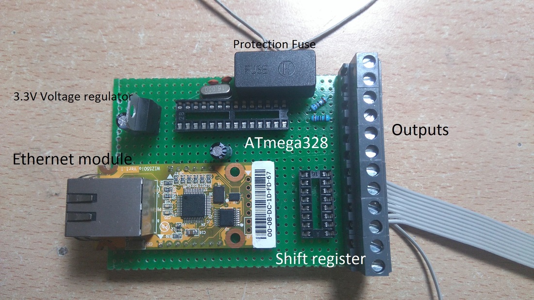
(ONLY) If you want to make your own custom - Arduino based - circuit you willalso need:
- LD1117V33 Voltage regulator (3.3V output)
- 16Mhz crystal osc
- 2x 22pF ceramic, 1x 0.1uF electrolytic capacitors
- 1x 10K resistor
- On/Off switch
- DC power jack
- 1A fuse box (just in case...)
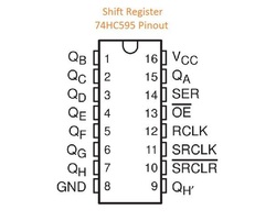
Shift Register 595 and outputs

The shift register will give to your Arduino an additional 8 digital outputs, by using only 3 pins on your board!
Here you can find a simple tutorial with the shift register 595 IC and Arduino uno board.
SR 595 and Arduino uno:
QA is the first output - QH is the 8th output. We will connect each output with one screw driver - terminal and with an LED through a 220 Ohm resistor.
(tip: You can use the QH' - pin 9 to add one more shift register ic and expand your outputs.)
Here you can find a simple tutorial with the shift register 595 IC and Arduino uno board.
SR 595 and Arduino uno:
- Pin 8 (GND) to GND
- Pin 10 (SRCLR') to 5V
- Pin 11 (SRCLK) to Arduino pin 6
- Pin 12 (RCLK) to Arduino pin 5
- Pin 13 (OE') to GND
- Pin 14 (SER) to Arduino pin 4
- Pin 16 (Vcc) to 5V
QA is the first output - QH is the 8th output. We will connect each output with one screw driver - terminal and with an LED through a 220 Ohm resistor.
(tip: You can use the QH' - pin 9 to add one more shift register ic and expand your outputs.)
|
|
Buttons and photoCell
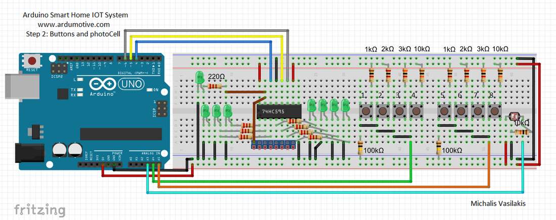
We will add 8 buttons, but we will use only 2 Arduino pins.
Find here a tutorial with multiple buttons through only one analog pin of Arduino board.
Find here a tutorial with a photocell (or photoresistor). Use one screw driver - terminal here to expand the sensor for the main circuit. Photocell will be connected to Arduino analog pin A3.
Find here a tutorial with multiple buttons through only one analog pin of Arduino board.
- Button BUS line 1 for output 1 to 4 to Arduino analog pin A4
- Button BUS line 2 for output 5 to 8 to Arduino analog pin A5
Find here a tutorial with a photocell (or photoresistor). Use one screw driver - terminal here to expand the sensor for the main circuit. Photocell will be connected to Arduino analog pin A3.
Ethernet Shield
|
|
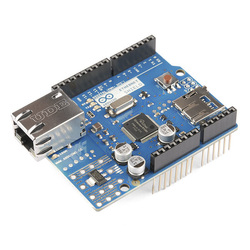
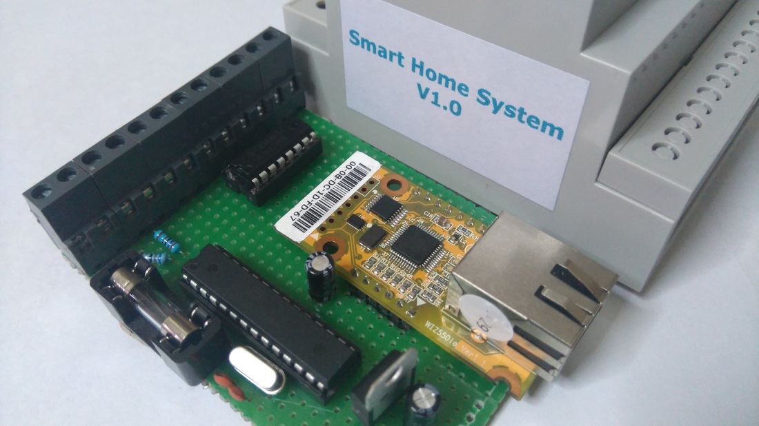
If you have an Ethernet Shield just attached it on the Arduino uno board.
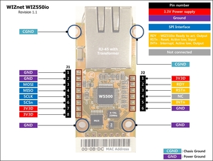
I am using the Wiznet Wiz550io ethernet module. It uses the same library with official Arduino Ethernet Shield (Ethernet.h), the only difference is that it has a unique MAC address.
I am using the Wiznet Wiz550io ethernet module. It uses the same library with official Arduino Ethernet Shield (Ethernet.h), the only difference is that it has a unique MAC address.
|
Some notes about SPI connection:
|
|
Note! Wiz550io must be powered from 3.3V output pin of Arduino uno! Do not use the 5V pin with this module!
The Code
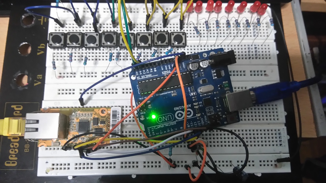
I also made my circuit in an breadboard first to test it. Here's the code, embedded using Codebender!
|
|
Try downloading the Codebender plugin and clicking on the "Run on Arduino" button to program your Arduino board with this sketch. And that's it, you've programmed your Arduino board directly from your browser! It's really amazing.
|
If you want you can make your changes in the sketch below by pressing the "Edit" button.
Try for example to change the labels of outputs, for example change "Output1" to "Kitchen Light" (line 164 value=\"Output 1\").
You can also change the network ip addresses to fit your network configuration.
Photo cell value (line 29) is setted to 300, but you can also change it by pressing the Edit button.
Note: If you will not use the Codebender IDE for programming your Arduino board you will need to manual install the SevenSeg library in your Arduino IDE. Where to find it? Search the web, don't ask me... Or just use the easy and simple way of Codebender.
User Interface
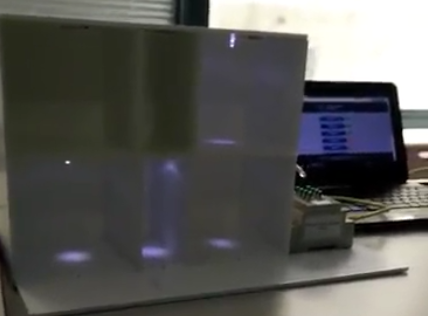
Plug the Ethernet cable to your rooter and turn on the Arduino smart home system (if you have it on an breadboard, just plug in the usb cable to your computer)
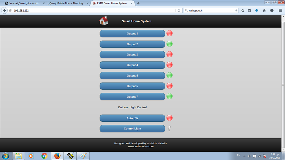
You can access the user interface from any device, just open one browser window and navigate to: 192.168.1.192
Press an button to "power on" an output. You will see that the red circle becomes green. That means that your output is setted to HIGH (you can see it also from the output led indicator). Press it again to turned it off. It's not just a changeable image from html page, but an answer from your Arduino! If an output fails to turned one, the output state indicator will remain red!
Outside local network - WAN
This page (192.168.1.192) can be access from any device in your local network. If you want to access your smart home system through internet you can simply add a rule in your rooter by opening a port (search the web like routers_name port forwarding). Remember that anyone can access your IOT device! You will also need a static ip or an dynamic DNS service to access your device anytime form anywhere. But it will also worked with your wan ip, until the next rooters restart (just search the web "find my ip"). Use this (wan) ip address to any device that is outside from your local network (important).
Outputs
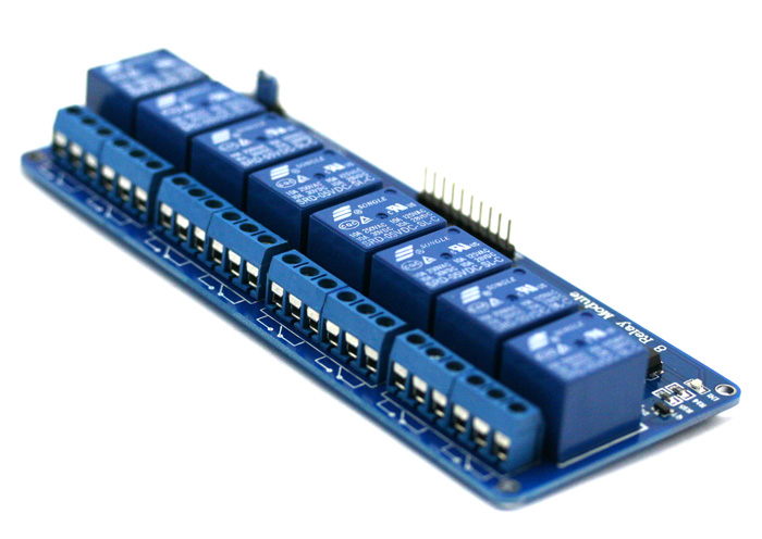
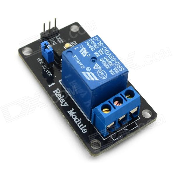
You can connect the outputs with 8 channel relay board or a single one, or tiger an RF module to control a relay module wirelessly. It is important to know what you are doing! One side of relay will be connected with high voltage (home) circuit, that means risk of electrocution!
- Connect each output with input signal of relay module.
Finally
Now you can make your own - Arduino based - customized circuit and close it in a small box.
I would like to see photos of your IOT home systems!
I hope you liked this, let me know in the comments below!
I would like to see photos of your IOT home systems!
I hope you liked this, let me know in the comments below!