|
Available Languages
|

|

|
Introduction |
Published date: 26/2/2018
|
|
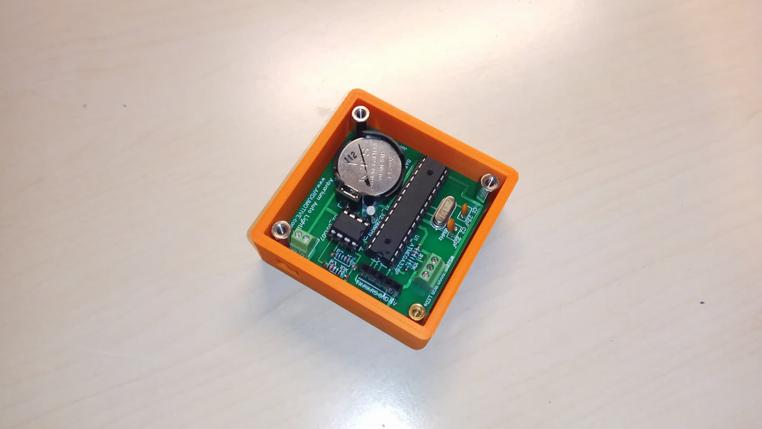
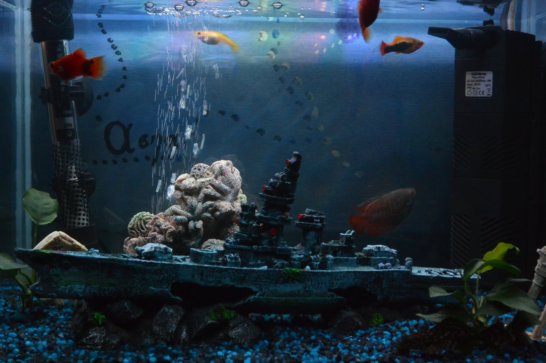
In this DIY guide I will show you how to make your own Arduino aquarium auto lighting system. In this project I decided to make my own PCB that is based on Arduino UNO microcontroller - Atmega328p.
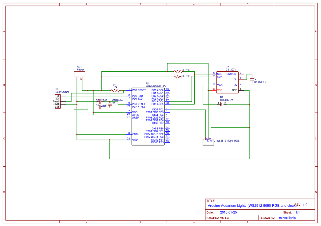
Bellow you will find the electronic schematic with PCB layout so you can easily produce it. |
The current time can be set for the first time (or when the coin battery is low) via the serial monitor. You can change the lighting change time or led color from code. Watch the video below:
What you will need - Hardware
You will also need a TTL to USB module or an Arduino UNO board for the programming procedure.
The circuit at EasyEDA, the free online circuit design platform
|

Arduino Aquarium Auto Lighting System
|
|
|
Enter here to see and make any changes to the above circuit.
EasyEDA is a free, zero- install, cloud-based EDA tool, designed to give electrical engineers, educators, engineering students and electronics hobbyists an Easier EDA Experience. It is easy to use circuit design, circuit simulator and PCB design that runs in your web browser. |
The code
Connect your circuit with TTL to USB module with 5 cables to the programming header. The pins RX and TX must be cross-connected.
NOTE: If you are using the Arduino UNO board make sure to remove the ATmega328 IC from it first and connect the headers RX to RX and TX to TX pins of the board. The RS pin must be connected to Arduino UNO reset pin.
NOTE: If you are using the Arduino UNO board make sure to remove the ATmega328 IC from it first and connect the headers RX to RX and TX to TX pins of the board. The RS pin must be connected to Arduino UNO reset pin.
1 2 3 4 5 6 7 8 9 10 11 12 13 14 15 16 17 18 19 20 21 22 23 24 25 26 27 28 29 30 31 32 33 34 35 36 37 38 39 40 41 42 43 44 45 46 47 48 49 50 51 52 53 54 55 56 57 58 59 60 61 62 63 64 65 66 67 68 69 70 71 72 73 74 75 76 77 78 79 80 81 82 83 84 85 86 87 88 89 90 91 92 93 94 95 96 97 98 99 100 101 102 103 104 105 106 107 108 109 110 111 112 113 114 115 116 117 118 119 120 121 122 123 124 125 126 127 128 129 130 131 132 133 134 135 136 137 138 139 140 141 142 143 144 | /* Arduino based - Aquarium Auto Lighing System * More info can be found at: http://www.ardumotive.com * Dev:Michalis Vasilakis Date:21/2/2018 Var:1.0 */ //Libraries (many thanks to Developers) #include <Adafruit_NeoPixel.h> #include <RTClib.h> //Constants const int DIN = 2; //Neopixel DIN pin to Arduino Pin 2 const int PIXELS = 29; //How many neopixel leds do you have? RTC_DS1307 rtc; //Create an object for DS1307 I2C library Adafruit_NeoPixel pixels = Adafruit_NeoPixel(PIXELS, DIN, NEO_GRB + NEO_KHZ800); //Create an object for NeoPixel library //Variables; int H,M; //H for hour and M for minutes String Time; // Use readTime(); Serial.print(Time); for printing the time in serial monitor //Variables For color setting boolean newColor = false; int r=0; int g=0; int b=0; //Following variables are used for the time setting from serial monitor boolean newMessage = false; boolean messageCompleted = false; char incomingByte; String command; //Delay without delay() for fade unsigned long previousMillis = 0; const long interval = 250; //Change this value (ms) void setup() { pixels.begin(); //Initialize the NeoPixel library rtc.begin(); //Initialize the RTC DS1307 library Serial.begin(9600); //This will run only if the rtc battery is low or rtc ic has wrong time set if (! rtc.isrunning()) { Serial.println("RTC is NOT running!"); // This line sets the RTC with an explicit date & time, for example to set // January 1, 2018 at 00:00am you would call: rtc.adjust(DateTime(2018, 01, 01, 00, 00, 0)); } Serial.println("Aquarium Auto Lighting System"); Serial.println("Visit the www.Ardumotive.com for more info \n"); readTime(); Serial.println(Time); Serial.println("- To set the time send '<SHH:MM>' (example: <S14:05>)"); } void loop() { setTime(); //Check for serial set command readTime(); //Change time and color values bellow if you want //From 00:00 to 07:00 if (H>=0 && H <7) { setColor(0,0,50); } //From 07:00 to 12:00 else if (H>=7 && H<12){ setColor(50,50,100); } else if( H>=12 && H<19){ setColor(180,180,180); } else if (H>=19 && H<21){ setColor(50,50,100); } } //Send color to led strip void setColor(int R,int G,int B){ while ((r!=R) || (g!=G) || (b!=B)){ setTime(); //Check for serial set command unsigned long currentMillis = millis(); if (currentMillis - previousMillis >= interval) { previousMillis = currentMillis; for(int i=0;i<PIXELS;i++){ // pixels.Color takes RGB values, from 0,0,0 up to 255,255,255 pixels.setPixelColor(i, pixels.Color(r,g,b)); pixels.show(); } if (r!=R && r<R){ r++; } else if (r!=R && r>R){ r--; } if (g!=G && g<G){ g++; } else if (g!=G && g>G){ g--; } if (b!=B && b<B){ b++; } else if (b!=B && b>B){ b--; } } } } //Read time from RTC void readTime(){ DateTime now = rtc.now(); H = now.hour(); M = now.minute(); Time = "Current time in RTC: " + String(H) + ":" + String(M); } //Set time, send <SHH:MM> (example <S05:00>) void setTime(){ if (Serial.available()){ incomingByte = Serial.read(); if(incomingByte=='>'){ messageCompleted=true; newMessage=false; } else if (incomingByte=='<'){ newMessage=true; } if (newMessage){ command.concat(incomingByte); } } if(messageCompleted){ //Set time if (command.charAt(1)=='S'){ int h = (command.substring(2,4)).toInt(); int m = (command.substring(5,7)).toInt(); rtc.adjust(DateTime(2018,01,01,h,m,0)); Serial.println("Done"); readTime(); Serial.println(Time); } command=""; messageCompleted=false; } } |
|
Download the code from here and open it with Arduino IDE. Inside you will also find the library file.
|
| ||
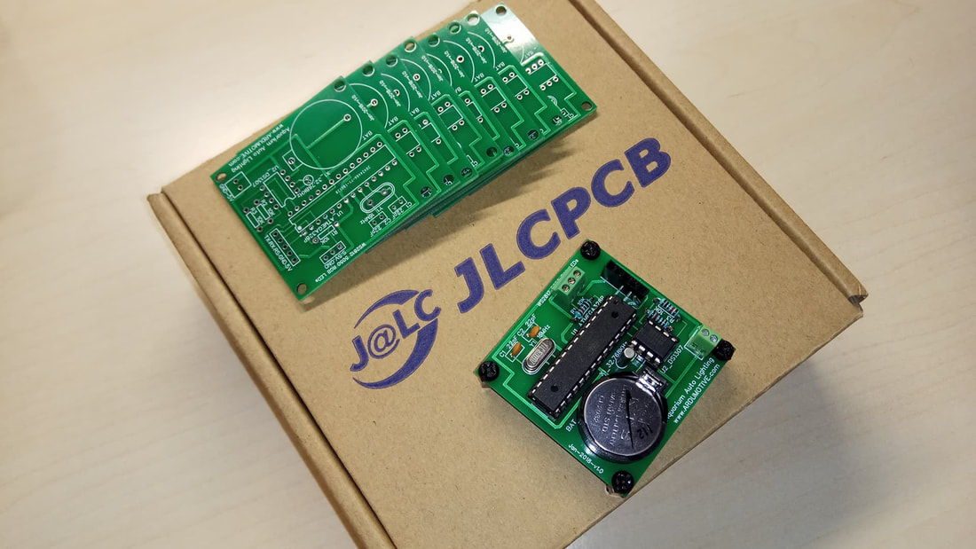
JLCPCB - Make your own circuit boad from 2$!
Enter here to produce your PCB board!
Use JLCPCB for $2 PCB Fabrication & 2-day Build Time, the quality is really good, check the below photo of our pcb board.
Use JLCPCB for $2 PCB Fabrication & 2-day Build Time, the quality is really good, check the below photo of our pcb board.
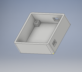
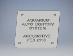
3D Parts
|
|
| aquabox1.stl |
Well Done!
I hope you liked this, let me know in the comments!!!